DC link components
9
9.1 Overview
Overview diagram
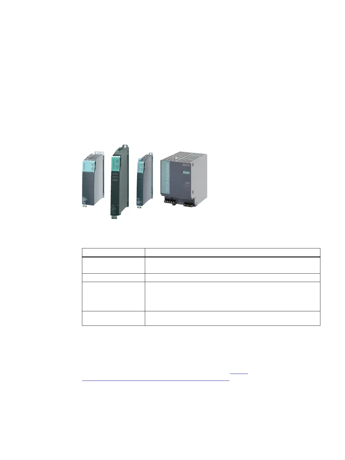
DC link components are installed in addition to the Line Modules and Motor Modules. They are
connected to other components via the DC link.
Figure9-1 DC link components
Table 9-1 DC link components
Component Function
Braking Module
Braking Module Compact
Specically stops drives in the event of power failure and limits the DC link
voltage
Capacitor Module Increases the DC link capacitance to buer brief line supply failures.
Control Supply Module Generates a 24VDC output voltage for the other components in the drive
line-up.
The Control Supply Module requires its own dedicated AC supply when
starting.
SITOP PSU400M Generates a 24VDC output voltage for the other components in the drive
line-up from the DC link.
More information
Information on Braking Modules, Capacitor Modules and Control Supply Modules is provided in
Chapter "DC link components" on the internet:
SINAMICSS120 Booksize Power Units Equipment Manual (
https://
support.industry.siemens.com/cs/ww/en/view/109781351)
Booksize power units
Equipment Manual, 09/2023, A5E53307519B AA 247
 Loading...


