8.4.1.2 Interfaces (lower side)
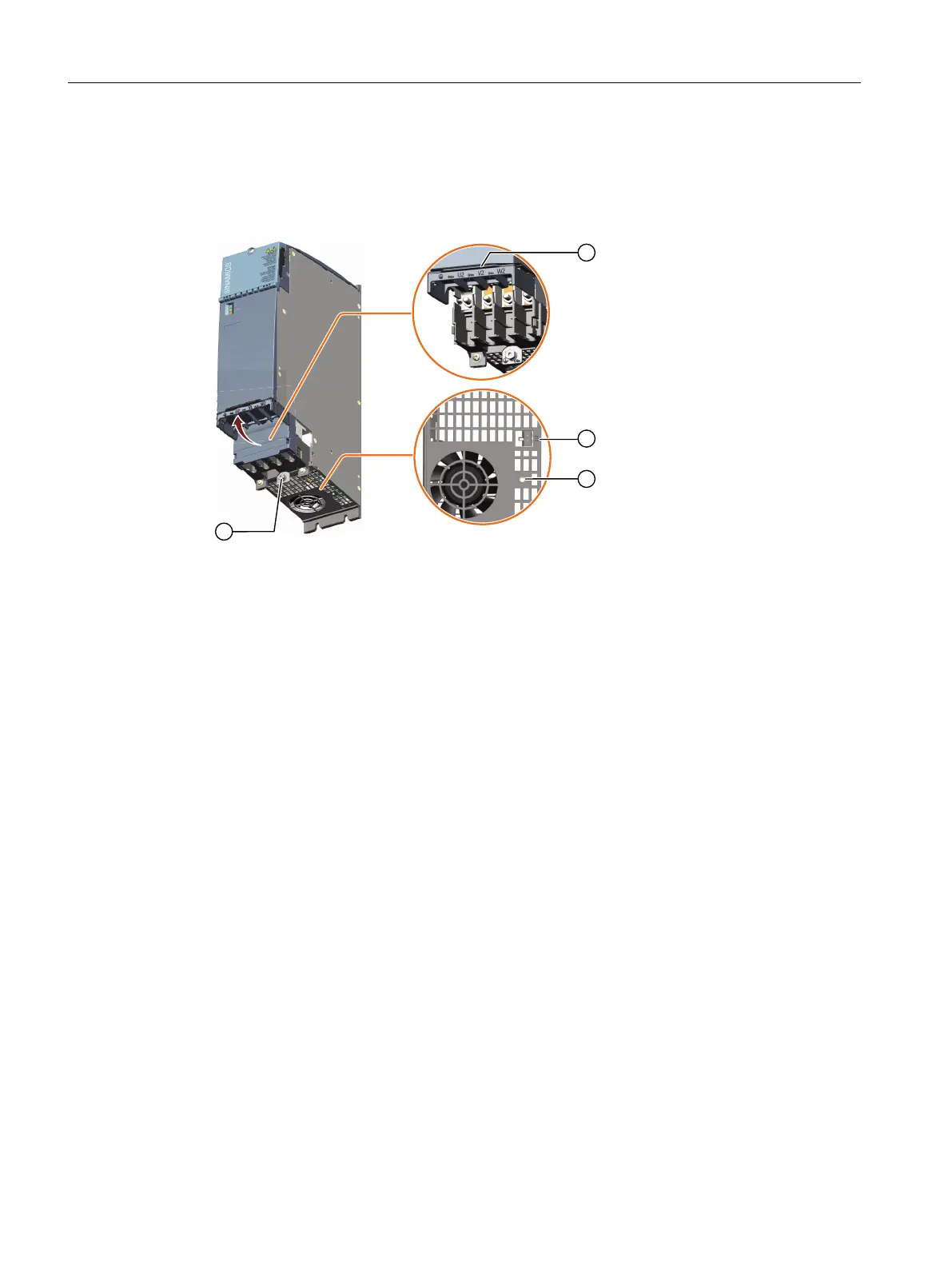
Overview diagram
① X1: Motor connection block
② X11: Connecting the holding brake
③ Threaded socket M4 for xing the shield connection clamp
④ Screw for the protective conductor connection of the Motor Module
Figure8-35 Interface overview, Motor Modules 45A and 60A (lower side)
8.4.1.3 X21EP terminals/temperature sensor
Overview
A temperature sensor and the signal cable for the enable pulses (EP) function are connected at
interface X21.
The plug-in terminals are included in the Terminal Kit of the Motor Module.
Motor Modules
8.4Motor Modules 45 A and 60 A
Booksize power units
188 Equipment Manual, 09/2023, A5E53307519B AA