Requirement
WARNING
Electric shock when the motor temperature sensor insulation fails
When connecting temperature sensors which are not isolated from the motor power circuit
according to safe electrical separation, arcing to the signal electronics may occur.
• Use motors whose temperature sensors have safe electrical separation.
• Use only connecting cables and connectors with safe electrical separation between the
cores of the temperature sensor and the cores of the power circuit.
• If safe electrical separation cannot be guaranteed (for linear motors or third-party motors,
for example), use a Sensor Module External (SME120 or SME125) or Terminal Module
TM120.
Only use the temperature sensor input of the Motor Module if the following conditions are
fullled:
• The connected motors are not equipped with an integrated DRIVE-CLiQ interface.
• The temperature values are not acquired via another component (Sensor Module Cabinet,
Sensor Module External, Terminal Module).
Description
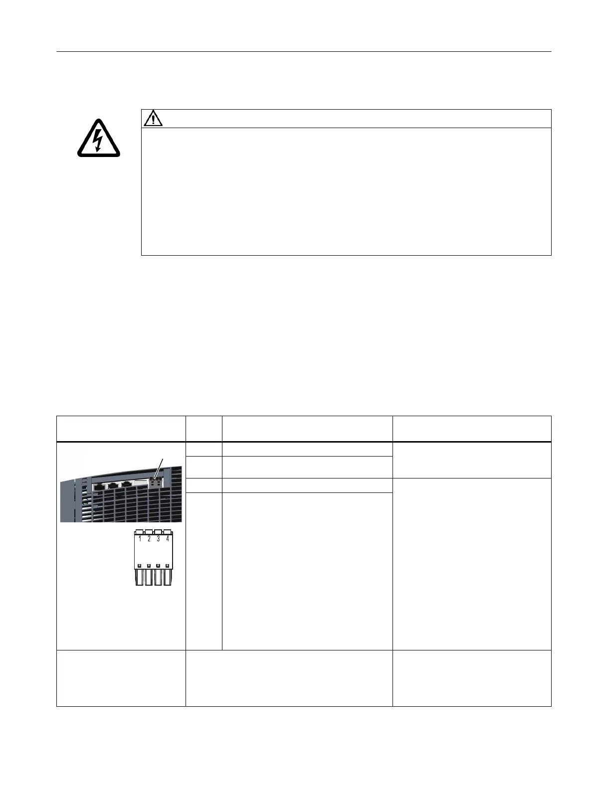
Table 8-19 X21: EP terminal/temperature sensor for Motor Modules 45 ... 200A
X21: EP terminals / tempera‐
ture sensor
Termi‐
nal
Designation Technical data
1 + Temp Temperature sensors
1)
: Pt1000 / PTC /
KTY84-130 / bimetallic switch with NC
contact
2 - Temp
3 EP + (Enable Pulses +) Voltage: -3…+30VDC
Electrical isolation: Yes
Input characteristic acc. to
IEC61131-2, type1 and type3
Input voltage (including ripple)
"1" signal: 11…30V
signal "0": -3…+5V
Input current
at 24VDC: 2.5...4mA
at < 1.5 mA: "0" signal reliably detected
Input delay
for "0" → "1": typ.25μs / max.50μs
for "1" → "0": typ.110μs+2μs/m /
max.150μs+4μs/m
4 EP M (Enable Pulses M)
Connectable cable cross-sec‐
tions
Rigid, exible
Flexible, with end sleeve without protective collar
Flexible, with end sleeve with protective collar
AWG / kcmil
0.25...1.5 mm
2
0.25...1.5mm
2 1)
0.25...0.75 mm
2
24…16
Motor Modules
8.4Motor Modules 45 A and 60 A
Booksize power units
Equipment Manual, 09/2023, A5E53307519B AA 189
 Loading...


