8.5.8 Mounting the shield connection plate
Overview
The shield connection plate is optional, and is mounted separately from the Motor Module with a
dened clearance on the control cabinet panel or on a mounting panel.
Requirement
The shield connection plate must be mounted before mounting the fan module to be able to
reach the lower mounting points on the mounting panel.
• The fan module has still not been installed in the component or was removed.
– Information about removing the fan module is provided in Chapter "Replace the fan
(Page242)".
Components required:
• Shield connection plate (85 A / 132 A: 6SL5166-1AF00-0AA0, 200 A: 6SL5166-1AH00-0AA0,
should be separately ordered)
• 2 x M6 screws with a max. head height of 7.7mm
• 2 x M6 washers
Procedure
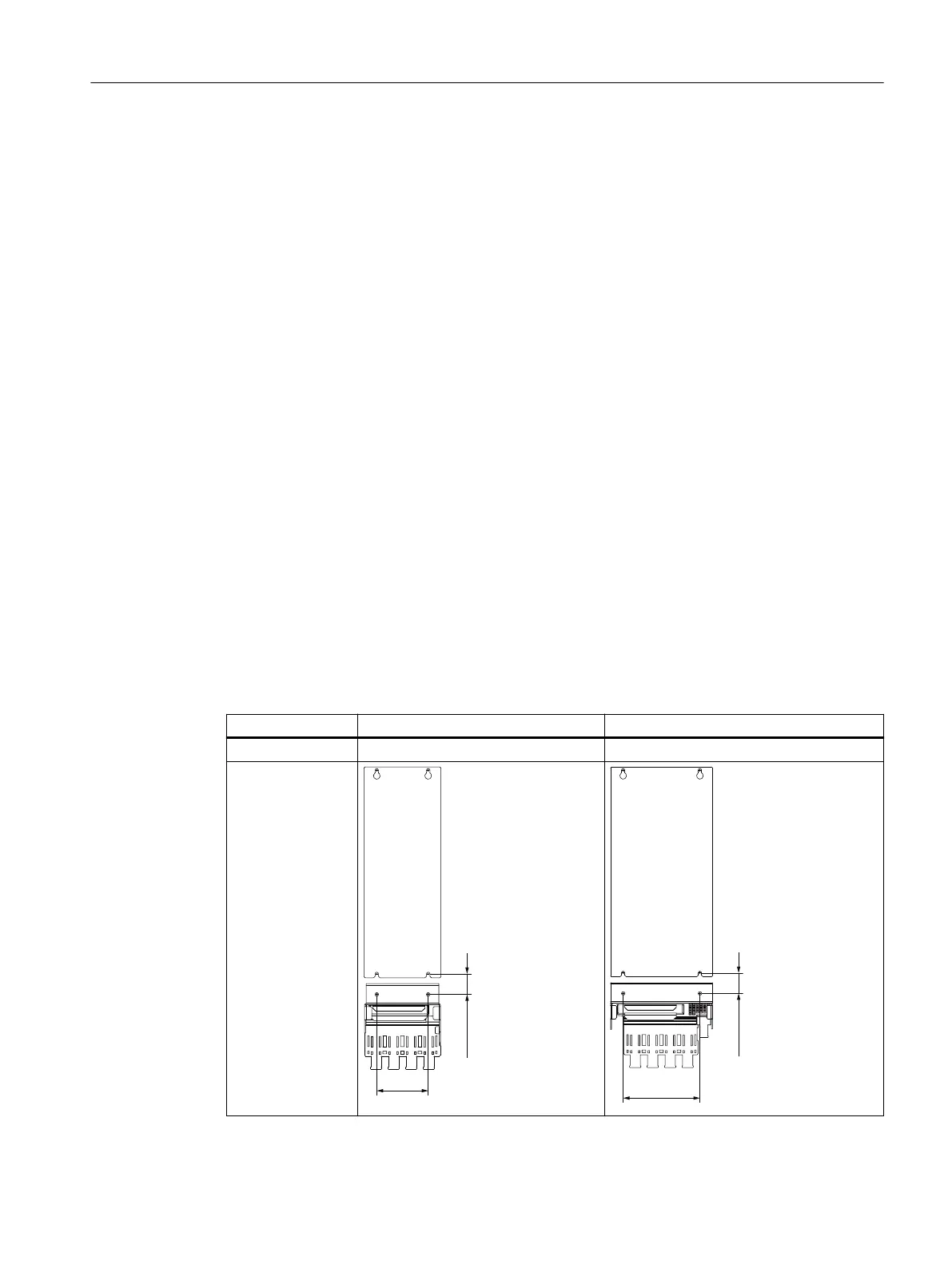
Table 8-39 Rear views of Motor Modules 85 A, 135 A and 200 A with shield connection plates in mm
and (inch)
Rated current 85A and 132A 200A
Width 150mm 200mm
Rear view
Motor Modules
8.5Motor Modules 85 A, 132 A and 200 A
Booksize power units
Equipment Manual, 09/2023, A5E53307519B AA 231
 Loading...


