8.5 Motor Modules 85 A, 132 A and 200 A
8.5.1 Interfaces and connections
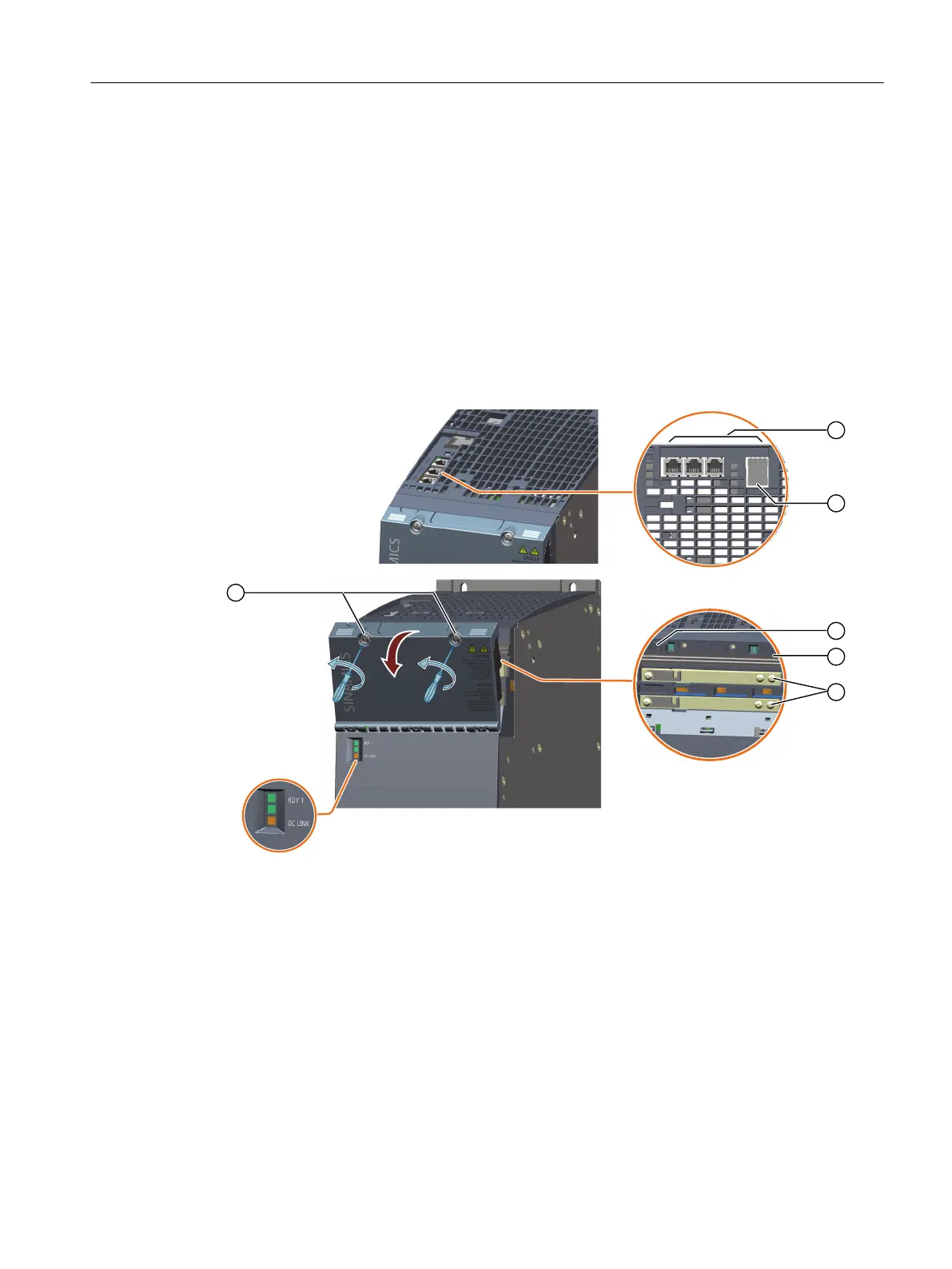
8.5.1.1 Interfaces (front and upper side)
Overview diagram
;
;
;;;
① X200 - X202: DRIVE-CLiQ interfaces
② X21: EP terminal/temperature sensor
③ Connection for the 24 V adapter (optional)
④ 24 V busbar
⑤ DC link busbars
⑥ Releasing the protective ap
Figure8-55 Interface overview, Motor Modules 85A, 132A and 200A (front and upper side)
Motor Modules
8.5Motor Modules 85 A, 132 A and 200 A
Booksize power units
Equipment Manual, 09/2023, A5E53307519B AA 211
 Loading...


