11.4.4.6 Connecting cables
Requirement
The following requirements must be satised to connect the cables to the DC link adapter:
• Dimension the cross-section of the connecting cables according to the current demand of all
connected components.
• The connecting cables must be appropriately protected.
• Use shrink-on sleeves to maintain touch protection for all non-insulated, live parts of cable
lugs and cables with a clearance to studs exceeding 32mm (1.26inch).
Required tools:
• Slotted screwdriver 1.0x5.5mm to release the protective ap
• Pliers for breaking out the cutout
• Socket wrench size10
Procedure
[PP
1POEILQ
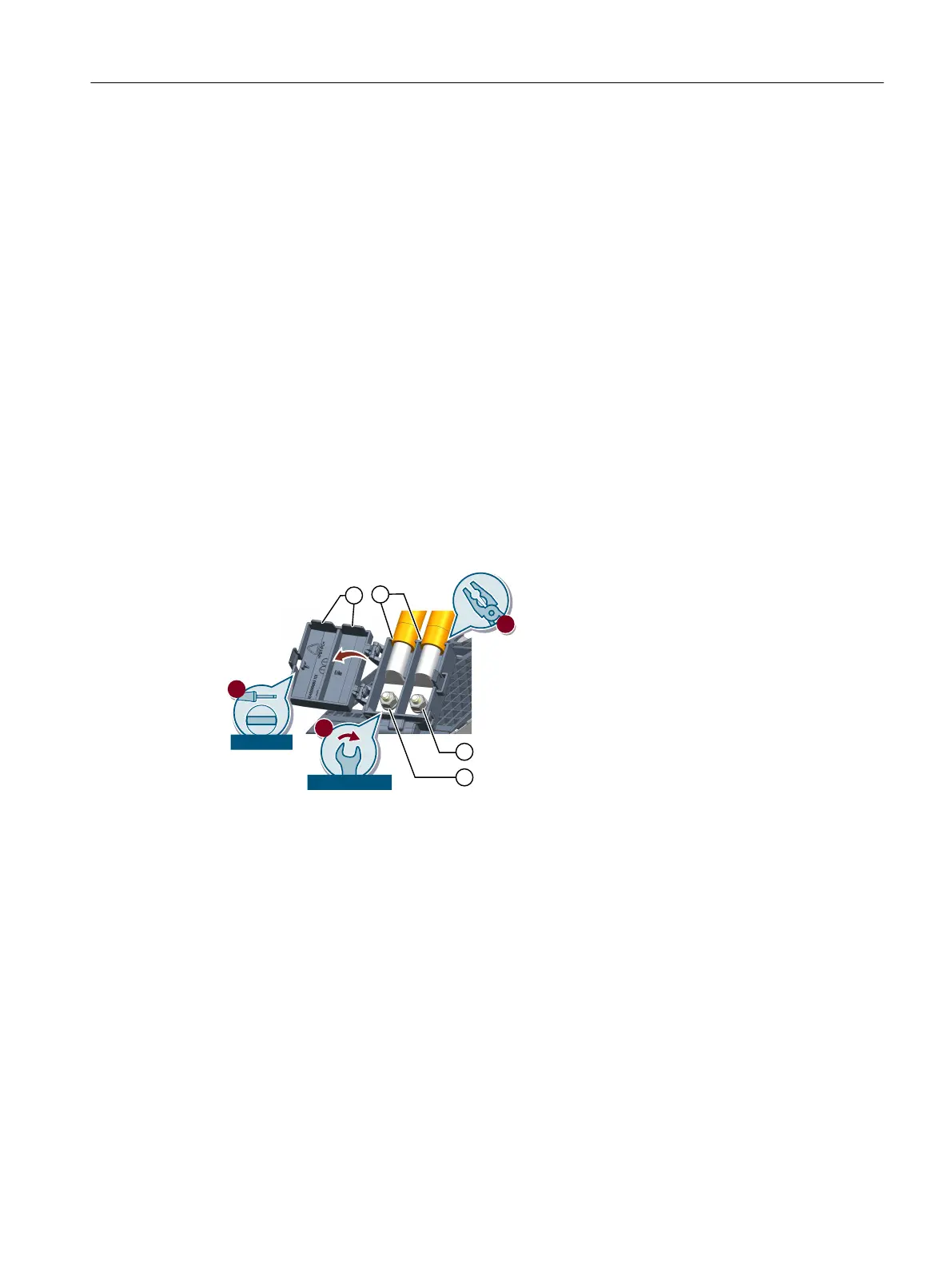
① Cutouts on the upper side of the housing (cover)
② Cutouts on the lower side of the housing (in this case, already broken out)
③ DCP
④ DCN
Figure11-16 Connecting cables to the 72A DC link adapter
Proceed as follows to connect the cables to the DC link adapter:
1. Attach a ring/pipe-type cable lug to the cables.
2. Open the cover of the DC link adapter using a slotted screwdriver 1.0x5.5mm.
Accessories
11.4DC link adapter
Booksize power units
Equipment Manual, 09/2023, A5E53307519B AA 291
 Loading...


