Description
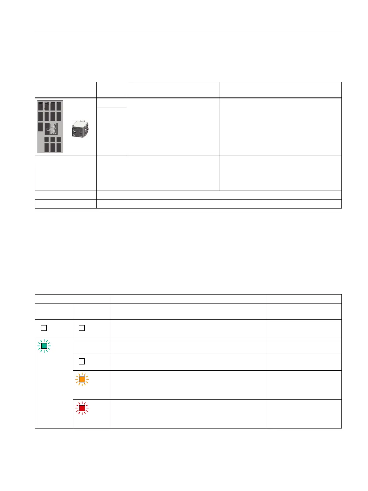
Table 8-21 X11: Holding brake connection for Motor Modules 45A and 60A
X11: Holding brake
connection
Terminal Designation Technical data
+ (BR+) Connecting the holding brake Module output voltage: 24 V DC
Max. load current: 2A
Minimum load current: 0.1A
- (BR-)
1)
Connectable cable
cross-sections
Rigid, exible
Flexible, with end sleeve without protective collar
Flexible, with end sleeve with protective collar
AWG / kcmil
0.08 … 2.5mm
2
0.25 … 2.5mm
2
0.25 … 1.5mm
2
28 ... 12
Stripped length 8...9mm (0.31...0.35inch)
Screwdriver Slotted screwdriver 0.5 x 3.5mm
1)
It is not permissible that you directly connect conductor BR- to electronics ground M.
8.4.2 LED description
Response of the LEDs in operation
Table 8-22 Meaning of the LEDs on the Motor Module
LEDs Description, cause Remedy
RDY1
for axis 1
DC LINK
The electronics power supply is missing or outside the permis‐
sible tolerance range.
Check the 24 V supply.
Green
–
1)
The component is ready for operation. Cyclic DRIVE-CLiQ com‐
munication is taking place.
–
The DC link voltage is <50V. –
Orange
The DC link voltage is present. –
Red
The DC link voltage lies above the permissible tolerance range. Check the line voltage.
Motor Modules
8.4Motor Modules 45 A and 60 A
Booksize power units
Equipment Manual, 09/2023, A5E53307519B AA 191
 Loading...


