8.5.2 LED description
Response of the LEDs in operation
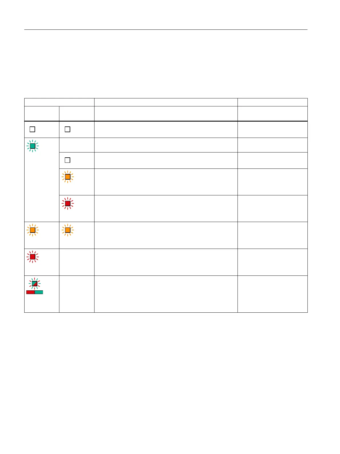
Table 8-33 Meaning of the LEDs on the Motor Module
LEDs Description, cause Remedy
RDY1
for axis 1
DC LINK
The electronics power supply is missing or outside the permis‐
sible tolerance range.
Check the 24 V supply.
Green
–
1)
The component is ready for operation. Cyclic DRIVE-CLiQ com‐
munication is taking place.
–
The DC link voltage is <50V. –
Orange
The DC link voltage is present. –
Red
The DC link voltage lies above the permissible tolerance range. Check the line voltage.
Orange Orange
DRIVE-CLiQ communication is being established. –
Red
–
1)
This component has at least one fault.
Remark:
The LED is controlled irrespective of the corresponding mes‐
sages being recongured.
Resolve and acknowledge
the fault.
Red/Green
(0.5Hz)
–
1)
Firmware is being downloaded. –
Motor Modules
8.5Motor Modules 85 A, 132 A and 200 A
Booksize power units
216 Equipment Manual, 09/2023, A5E53307519B AA
 Loading...


