Procedure
The holding brake requires a typical voltage of 24 V ±10%. Proceed as follows to determine the
input voltage of the Motor Module that matches the holding brake:
1. Take the holding brake voltage and its tolerance from the motor technical data.
– Take into account possible voltage drops in the Motor Module and along the supply cable.
Use a Control Supply Module or a controlled DC power supply whose setpoint is set to at
least 26V.
– Note that there are holding brakes that close again when the maximum voltage is
exceeded.
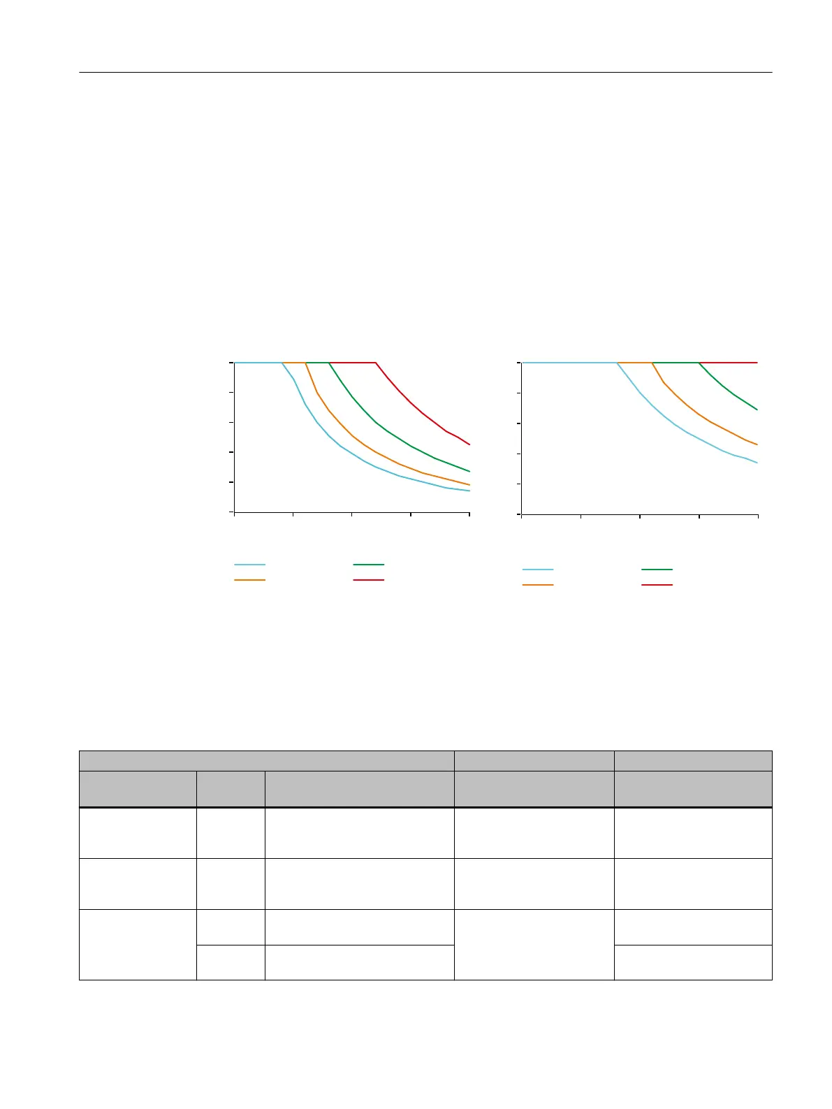
2. Check the permissible cable length using the following diagrams.
)PMEJOHCSBLFDVSSFOU<">
$BCMFMFOHUI<N>
PPt
PPt
PPt
PPt
24 V input voltage
$BCMFMFOHUI<N>
)PMEJOHCSBLFDVSSFOU<">
PPt
PPt
PPt
PPt
26 V input voltage
4.10.3 Selecting power supply units
The following devices meet the applicable requirements of EN 60204-1 and they are
recommended:
Recommended power supplies: SITOP Power modular
Rated output cur‐
rent [A]
Phases Rated input voltage [V]
Operating voltage range [V]
Short-circuit current [A] Article number
5 1/ 2 AC 120 … 230/230 … 500
85 … 264/176 … 550
approx. 5.5(running up)
typ. 15 for 25 ms (in opera‐
tion)
6EP1333-3BA00-8AC0
10 1/ 2 AC 120 … 230/230 … 500
85 … 264/176 … 550
approx. 12(running up)
typ. 30 for 25 ms (in opera‐
tion)
6EP1334-3BA00-8AB0
20 1/ 2 AC 120 / 230
85 … 132/176 … 264
approx. 23(running up)
typ. 60 for 25 ms (in opera‐
tion)
6EP1336-3BA00-8AA0
3 3AC 230/400… 288/500
320… 550
6EP1436-3BA00-8AA0
Application planning
4.1024 V DC supply voltage
Booksize power units
Equipment Manual, 09/2023, A5E53307519B AA 49
 Loading...


