Description
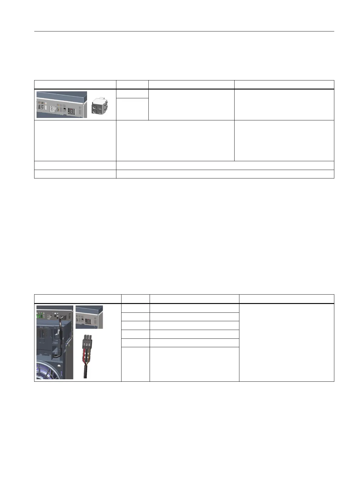
Table 8-31 X11: Holding brake connection for Motor Modules 85A, 132A and 200A
X11: Holding brake connection Terminal Designation Technical data
+ (BR+) Connecting the holding brake Module output voltage: 24 V DC
Max. load current: 2A
Minimum load current: 0.1A
- (BR-)
1)
Connectable cable cross-sec‐
tions
Rigid, exible
Flexible, with end sleeve without protective col‐
lar
Flexible, with end sleeve with protective collar
AWG / kcmil
0.08 … 2.5mm
2
0.25 … 2.5mm
2
0.25 … 1.5mm
2
28 ... 12
Stripped length 8...9mm (0.31...0.35inch)
Screwdriver Slotted screwdriver 0.5 x 3.5mm
1)
It is not permissible that you directly connect conductor BR- to electronics ground M.
8.5.1.6 X12 fan connection
Overview
The interface is located on the lower side of the Motor Module. The fan connection plug is pre-
assembled and premounted on the fan module.
Description
Table 8-32 X12: Fan connection for Motor Modules 85A, 132A and 200A
X12: Fan connection Terminal Designation Technical data
1 Fan connection+ (red) Voltage: 48VDC
2 N/A
3 Fan connection- (black)
4 N/A
5 PWM input (brown)
6 Tacho signal (yellow)
Motor Modules
8.5Motor Modules 85 A, 132 A and 200 A
Booksize power units
Equipment Manual, 09/2023, A5E53307519B AA 215
 Loading...


