11.4.6.3 Connectable cable cross-sections
Description
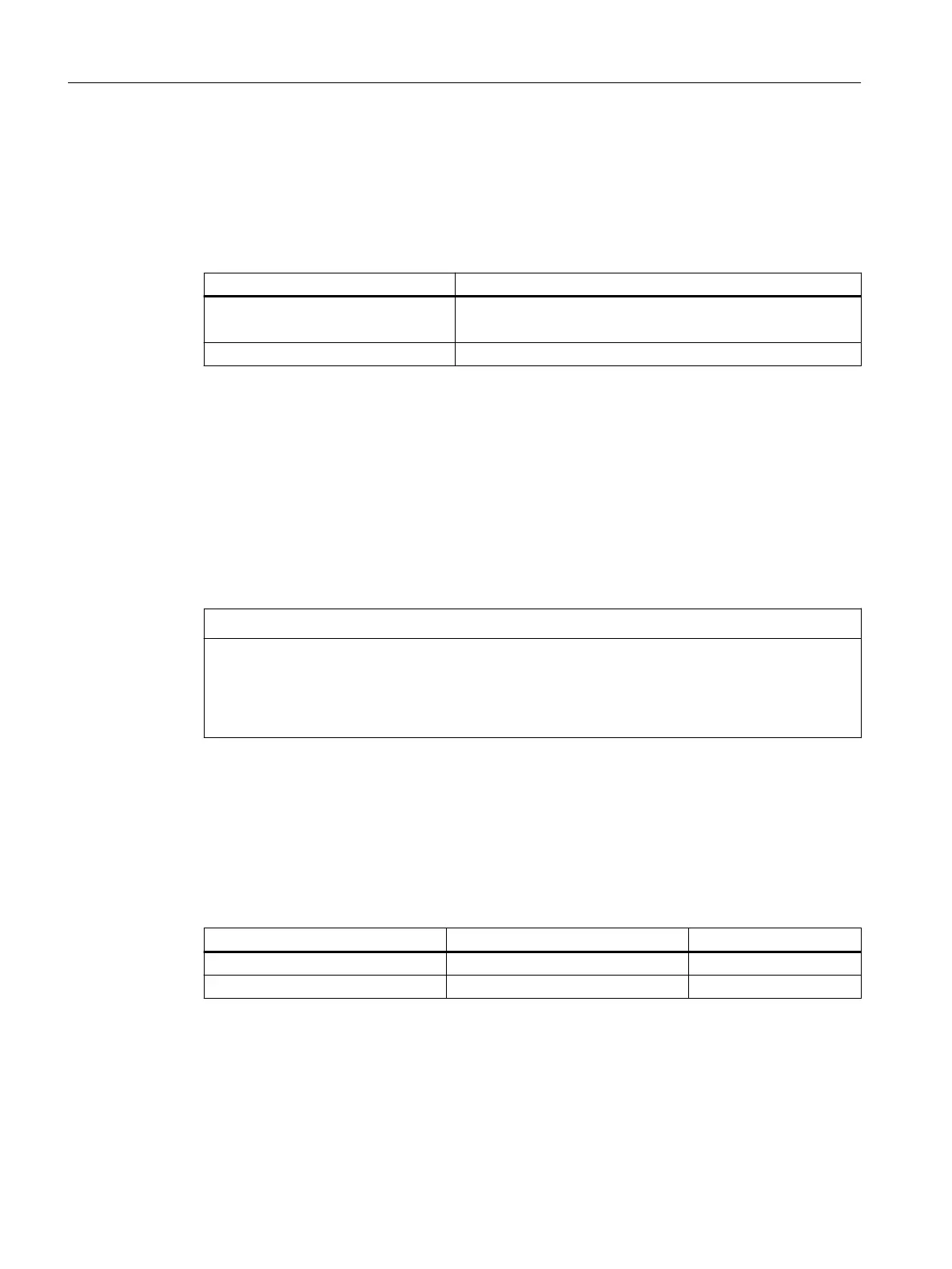
Table 11-12 Conductor cross-sections of the cable for the multi-tier DC link adapter 150/200A
Feature Cable cross-sections
Cable cross-sections Single core connection:
35...120mm
2
(AWG4...4/0)
Stripped length 27mm
11.4.6.4 Mounting types of the DC link adapter
Overview
Various options are available to mount the DC link adapter for a multi-tier conguration. These
depend on the width of the components used as well as how the drive line-up is congured.
Requirement
NOTICE
Damage when mounting using 2screws
For DC link adapters that are mounted using 2screws, currents above 150A result in a high
temperature rise. This can damage the DC link adapter and the component.
• You must limit the current to 150A if the DC link adapter is mounted using 2 screws.
Description
Depending on the conguration of the drive line-up, the DC link adapter can be mounted onto
the component to the far left or to the far right.
Depending on the mounting side and width of the component, 2 or 4 screws are available for
mounting:
Mounting left Mounting right Number of screws
Modules 50mm - 200mm Modules 50mm, 100mm 2
- Modules 150mm, 200mm 4
Accessories
11.4DC link adapter
Booksize power units
300 Equipment Manual, 09/2023, A5E53307519B AA
 Loading...


