The Motor Modules are equipped with a motor and holding brake connection:
• X1: Motor and holding brake connection for Single Motor Modules 3A to 30A
• X1 - X2: Motor and holding brake connection for Double Motor Modules 2x3A to 2x18A
Description
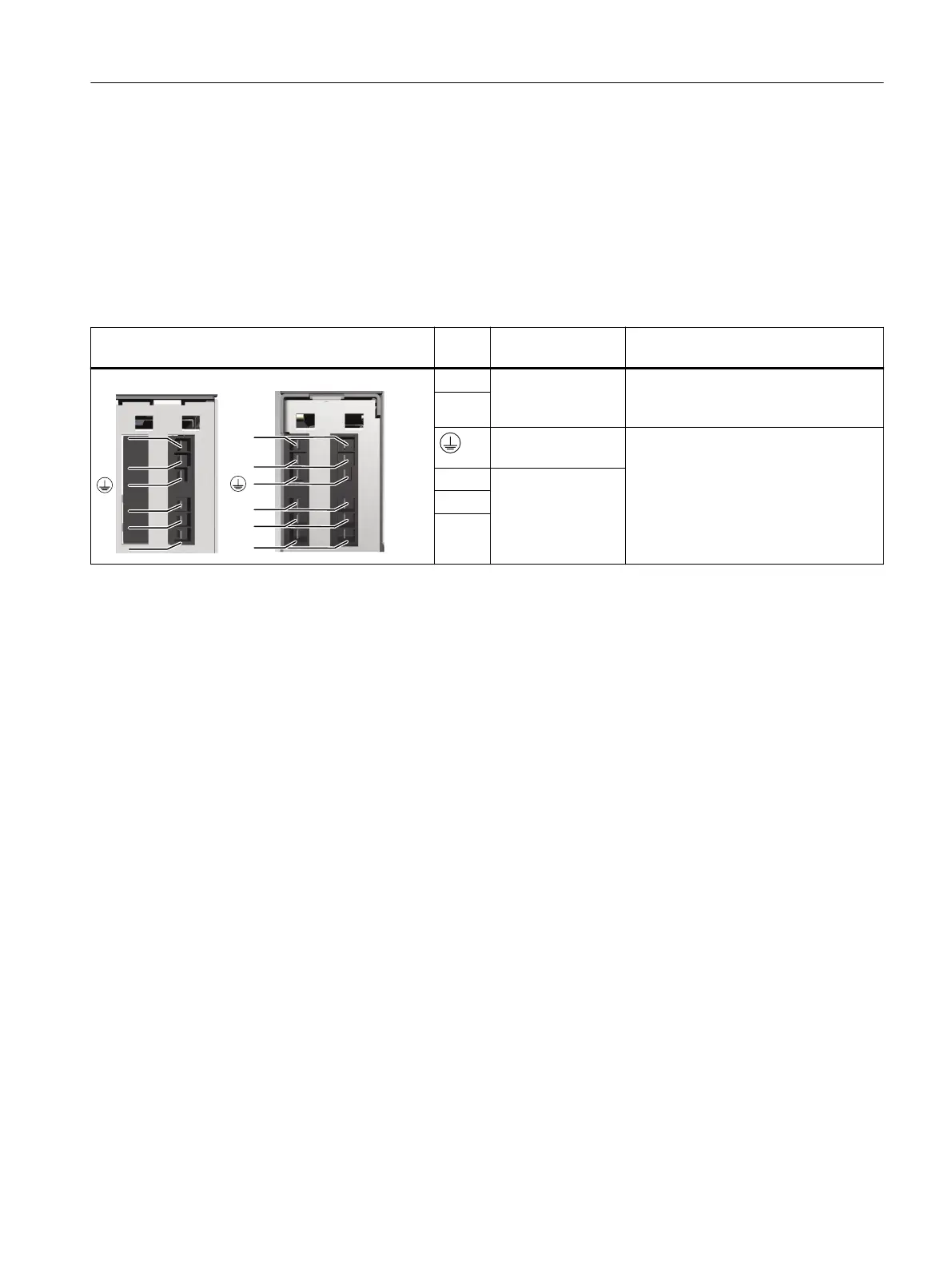
Table 8-4 X1 - X2: Motor and holding brake connection for Motor Modules 3 ... 30A, 2x3 ... 2x18A
X1 - X2: Motor and holding brake connection Termi‐
nal
Designation Technical data
%U
%U²
8
9
:
;
;;
%U
%U²
8
9
:
BR+ Holding brake con‐
nection
1)
Output voltage: 24 V DC
Maximum load current: 2A
Minimum load current: 0.1A
BR-
Motor PE/ground
connection
U2 Motor connection
V2
W2
1)
The holding brake must be connected via outputs BR+ and BR- of connector X1 or X2. It is not permissible that the BR-
conductor is directly connected to the electronics ground M.
Motor Modules
8.3Motor Modules 3 ... 30 A and 2x3 ... 2x18 A
Booksize power units
Equipment Manual, 09/2023, A5E53307519B AA 157
 Loading...


