Procedure
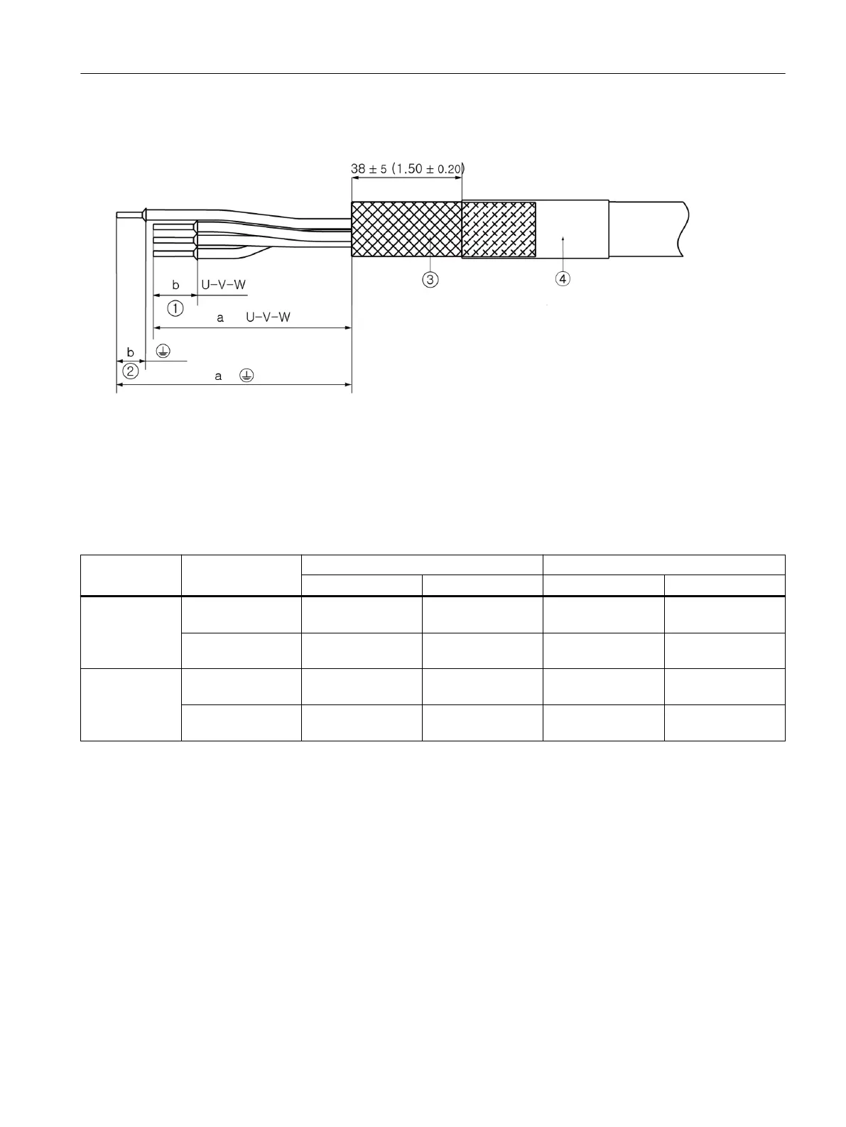
① Cores U-V-W
② Protective conductor core
③ Protective braided shield
④ Shrink-on sleeve
Figure7-12 Line supply cable for Smart Line Modules
Table 7-10 Core and stripped lengths as a function of the cable cross-section, data in mm and (inch)
Connection
plug
Connection 6mm² AWG10 10mm
2
/16 mm
2
AWG 8/AWG6
a b a b
Plug with
screw connec‐
tion
U1, V1, W1 90 +2/-3
(3.54+0.08/-0.12)
12 ±0.5
(0.47 ±0.02)
90 +2/-3
(3.54+0.08/-0.12)
15 ±0.5
(0.59 ±0.02)
Protective conduc‐
tor
95 +2/-3
(3.74 +0.08/-0.12)
12 ±0.5
(0.47 ±0.02)
95 +2/-3
(3.74 +0.08/-0.12)
15 ±0.5
(0.59 ±0.02)
Plug with push-
in connection
U1, V1, W1 95 +2/-3
(3.74+0.08/-0.12)
12 ±0.5
(0.71 ±0.02)
95 +2/-3
(3.74+0.08/-0.12)
18 ±0.5
(0.71 ±0.02)
Protective conduc‐
tor
100 +2/-3
(3.94 +0.08/-0.12)
12 ±0.5
(0.71 ±0.02)
100 +2/-3
(3.94 +0.08/-0.12)
18 ±0.5
(0.71 ±0.02)
To connect the line supply cable at the connection plug, prepare these as subsequently
described:
1. Remove 110mm (4.33in) of cable sheath with a tolerance of ±5mm (±0.20in).
2. Shorten the protective braided shield and fold it back by the same length.
3. Fix the protective braided shield. Preferably use a shrink-on sleeve with hot melt adhesive.
4. Shorten the single cores to length "a" according to the table above. The stripped lengths of
the line supply cables are the same for all cross-sections.
5. Remove the insulation of the single cores to length "b" according to the table above.
Smart Line Modules
7.12Line connection
Booksize power units
Equipment Manual, 09/2023, A5E53307519B AA 131
 Loading...


