Procedure
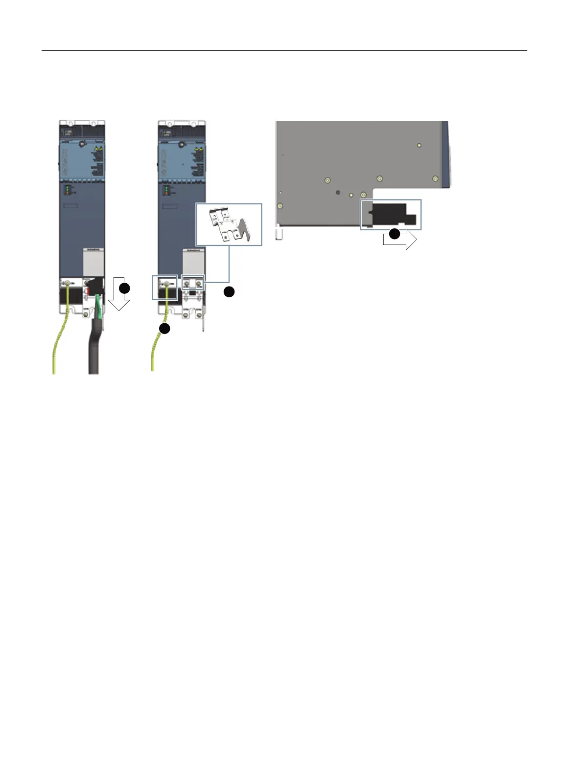
Figure7-21 Replacing the fan for Smart Line Modules 16kW - 24kW
Replace the existing fan module as follows:
1. If there is an additional shield connection plate tted, remove the shield connection clamp.
2. Release the connection plug catch and withdraw the plug from the Smart Line Module.
3. If necessary, remove the shield connection plate from the Smart Line Module. Torx
screwdriver TX20
4. Release the protective conductor from the Smart Line Module. Torx screwdriver TX25
5. Withdraw the fan module from the Smart Line Module toward the front.
6. Insert a new fan module into the Smart Line Module. The power supply for the fan is
automatically established.
7. The Smart Line Module is connected up again by following the reverse procedure once the
new fan module has been installed.
– Screw the shield connection plate into place. Tightening torque: 3Nm(26.6lbfin)
– Connect the protective conductor to the Smart Line Module. Tightening torque:
3Nm(26.6lbfin)
– Fully reinsert the connection plug into the Smart Line Module until it audibly latches.
– Secure the line supply cable to the shield connection plate using a cable tie.
– If you are using a shielded line supply cable, connect the line supply cable shield using the
hose clamp or shield connection clamp.
Smart Line Modules
7.14Service and maintenance
Booksize power units
144 Equipment Manual, 09/2023, A5E53307519B AA
 Loading...


