Procedure
E
E
E
%5
E
%5
D%5
D%5
D89:
89:
D
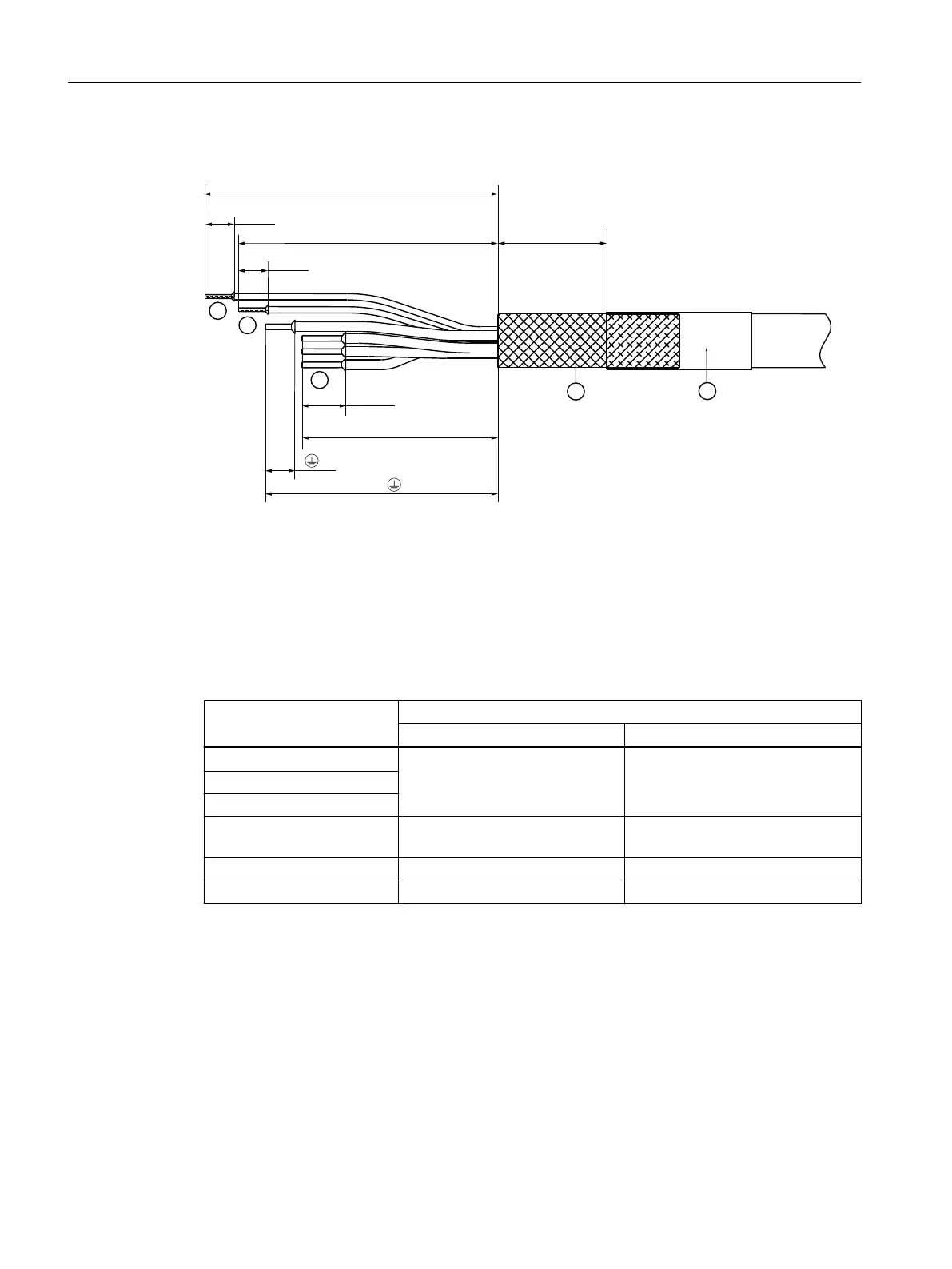
① Cores U2-V2-W2
② Protective conductor core
③ Holding brake cores
④ Protective braided shield
⑤ Shrink-on sleeve
Figure8-26 Design of the motor connection cable for Motor Modules 3 ... 30 A and 2 x 3 A ... 2 x 18 A
Table 8-13 Stripped lengths for motor connection cable cores
Connection Stripped length, in mm and (inch)
a b
U2 55 +2/-3 (2.17 +0.08/-0.12) 12 ±0.5 (0.47 ±0.02)
V2
W2
Protective conductor to the
motor
63 +2/-3 (2.48+0.08/-0.12) 12 ±0.5 (0.47±0.02)
BR- to the holding brake 73 ±5 (2.87±0.20) 12 ±0.5 (0.47±0.02)
BR+ to the holding brake 79 ±5 (3.11±0.20) 12 ±0.5 (0.47±0.02)
To connect the power cables at the connection plug, prepare these as subsequently
described:
1. Remove the cable sheath to a length of 85 mm (3.35 in) with a tolerance of ±5 mm (±0.2 in).
2. Shorten the protective braided shield and fold it back by the same length.
– If you use a motor connection cable with brake cores, then you must unbraid the
protective braided shield of the brake cores. This is then folded back against the outer
shield.
3. Fix the protective braided shield. Preferably use a shrink-on sleeve with hot melt adhesive.
Motor Modules
8.3Motor Modules 3 ... 30 A and 2x3 ... 2x18 A
Booksize power units
178 Equipment Manual, 09/2023, A5E53307519B AA
 Loading...


