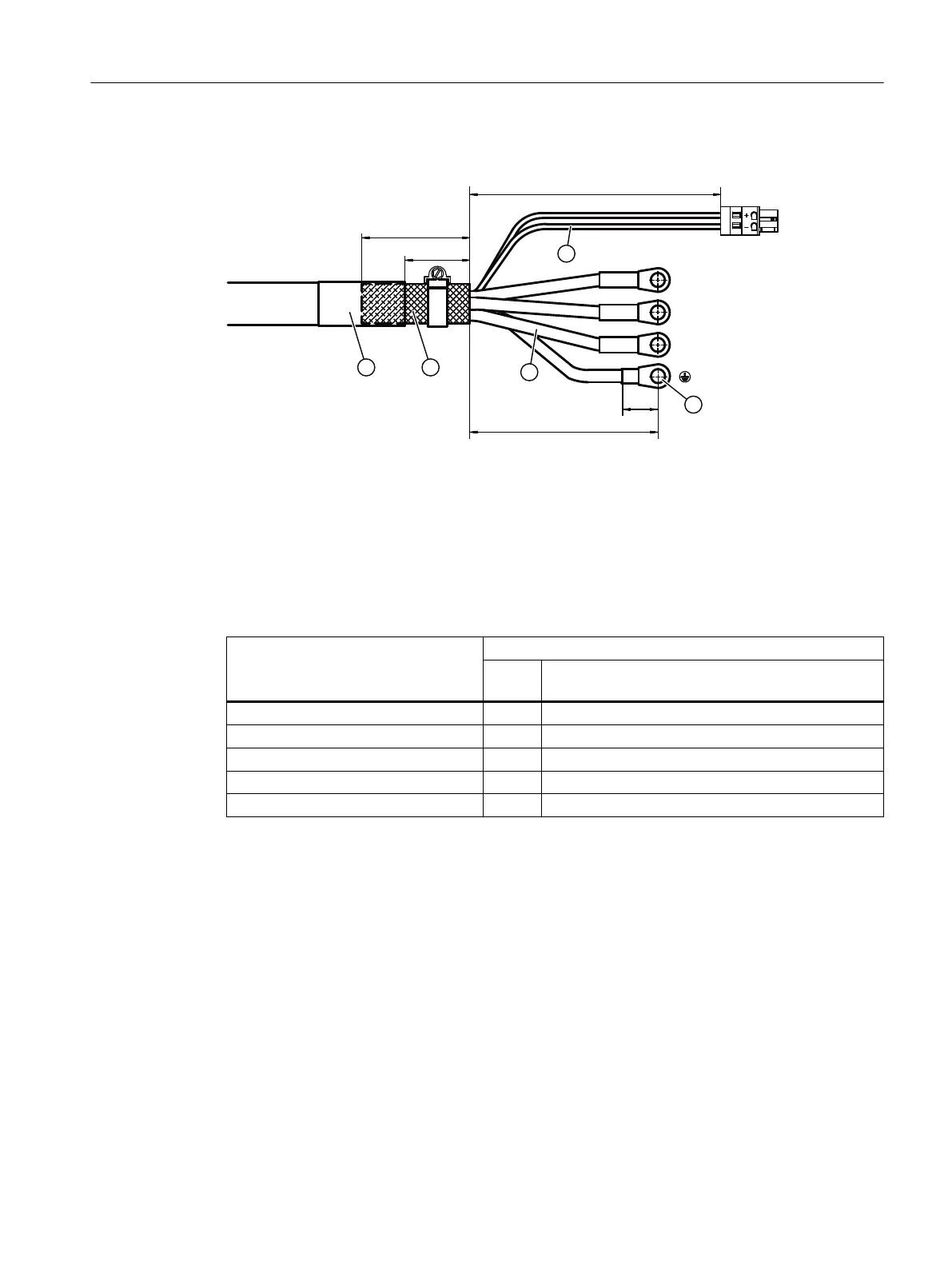
Procedure
① Holding brake cores
② Cores U2, V2, W2 and protective conductor
③ Ring or pipe-type cable lug M8
④ Protective braided shield
⑤ Shrink-on sleeve
Figure8-82 Design of the motor connection cable for Motor Modules 85A, 132A and 200A
Table 8-42 Stripped lengths for motor connection cable cores
Connection Stripped length, in mm and (inch)
Connection using a shield connection clamp or
hose clamp
BR+, BR- a 210 ±10 (8.3 ±0.4)
U2, V2, W2, protective conductor b 175 ±5 (6.9 ±0.2)
Pipe-type cable lug c depending on the cable lug used
Shield d 60 ±5 (2.4 ±0.2)
folded back protective braided shield e 100 ±10 (3.9 ±0.4)
To connect the motor connection cable, prepare this as subsequently described:
1. Remove 220mm (8.66in) of cable sheath with a tolerance of ±10mm (±0.4in).
2. Shorten the protective braided shield and fold it back by the same length.
– If you use a motor connection cable with brake cores, then you must unbraid the
protective braided shield of the brake cores. This is then folded back against the outer
shield.
3. Fix the protective braided shield. Preferably use a shrink-on sleeve with hot melt adhesive.
4. Shorten the single cores to length "a" according to the table above. The stripped lengths of
the motor cables are the same for all cross-sections.
5. Remove length "b" of the insulation from the single cores according to the table above.
6. Attach a ring or pipe-type cable lug to the stripped end area.
Motor Modules
8.5Motor Modules 85 A, 132 A and 200 A
Booksize power units
Equipment Manual, 09/2023, A5E53307519B AA 237
 Loading...


