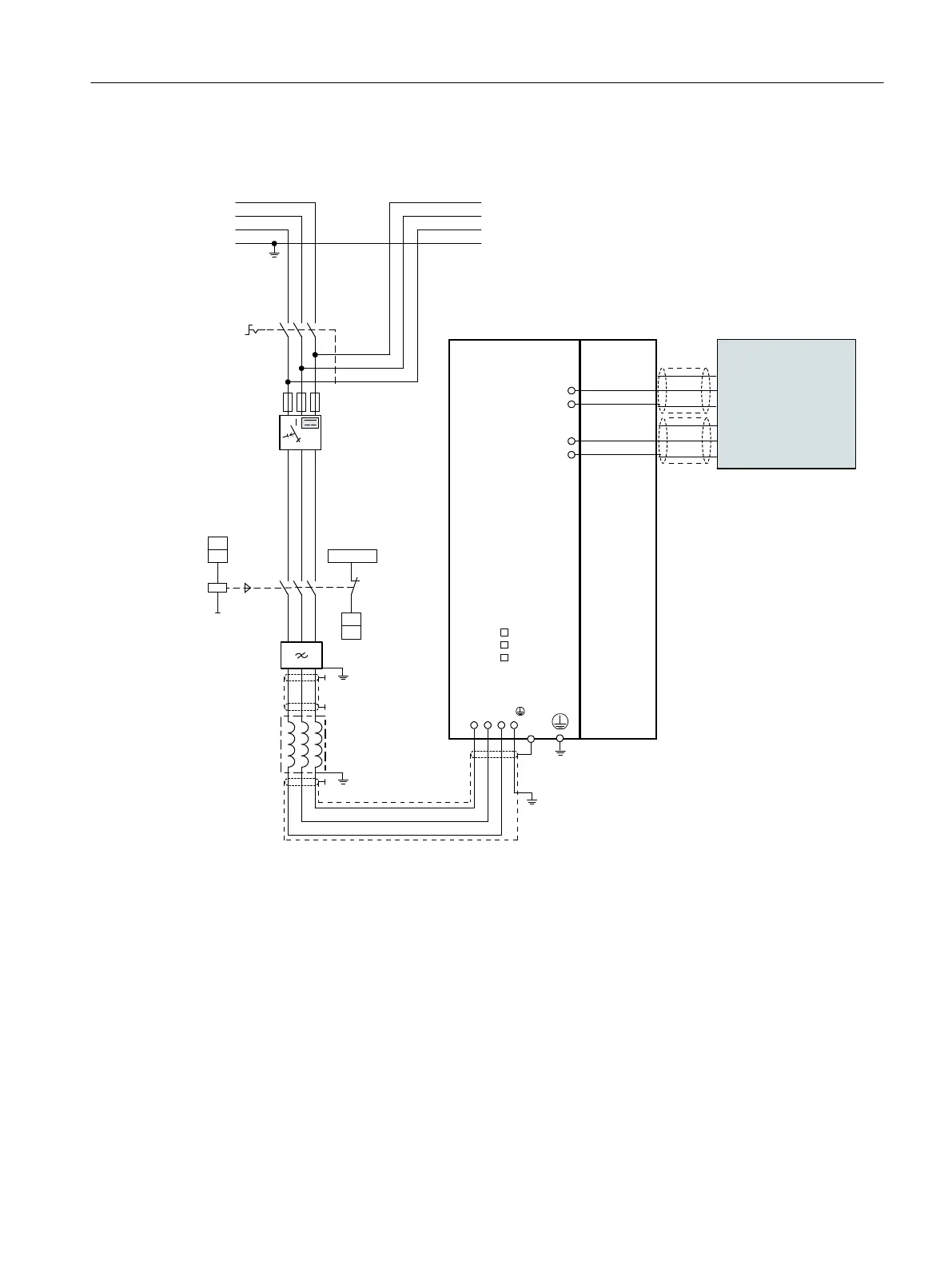
The SITOP PSU400M is connected to the drive lineup via the DC link adapter and via the 24 V
terminal adapter.
Main switch
Line contactor
(optional)
Fuses
Line filter
Line reactor
Output
Input
5)
3)
DC 24 V
CU
DI
CU
DO
W1V1U1
1)
PE
1L1
1L2
1L3
PE
L1
L2
L3
LEDs
DC LINK
READY
DCP
DCN
+
M
Smart Line
Module
4)
2)
Motor
Module
SITOP PSU400M
DC 24 V
DC 600 V
1 ... n Motor Modules
1)
4)
4)
Residual current device (RCD)
(optional)
1) DI/DO, controlled by the Control Unit
2) No additional load permitted downstream of the line contactor.
3) Observe the current-carrying capacity of the DO. It may be necessary to use an output coupling link.
4) Contact is established through the rear panel or shield rails in accordance with the EMC installation guideline.
5) A DC link adapter is required for connection to the DC link. The 24 V connection is made via a 24 V terminal adapter.
Figure9-2 Connection example, SITOP PSU400M
DC link components
9.2SITOP PSU400M
Booksize power units
Equipment Manual, 09/2023, A5E53307519B AA 251
 Loading...


