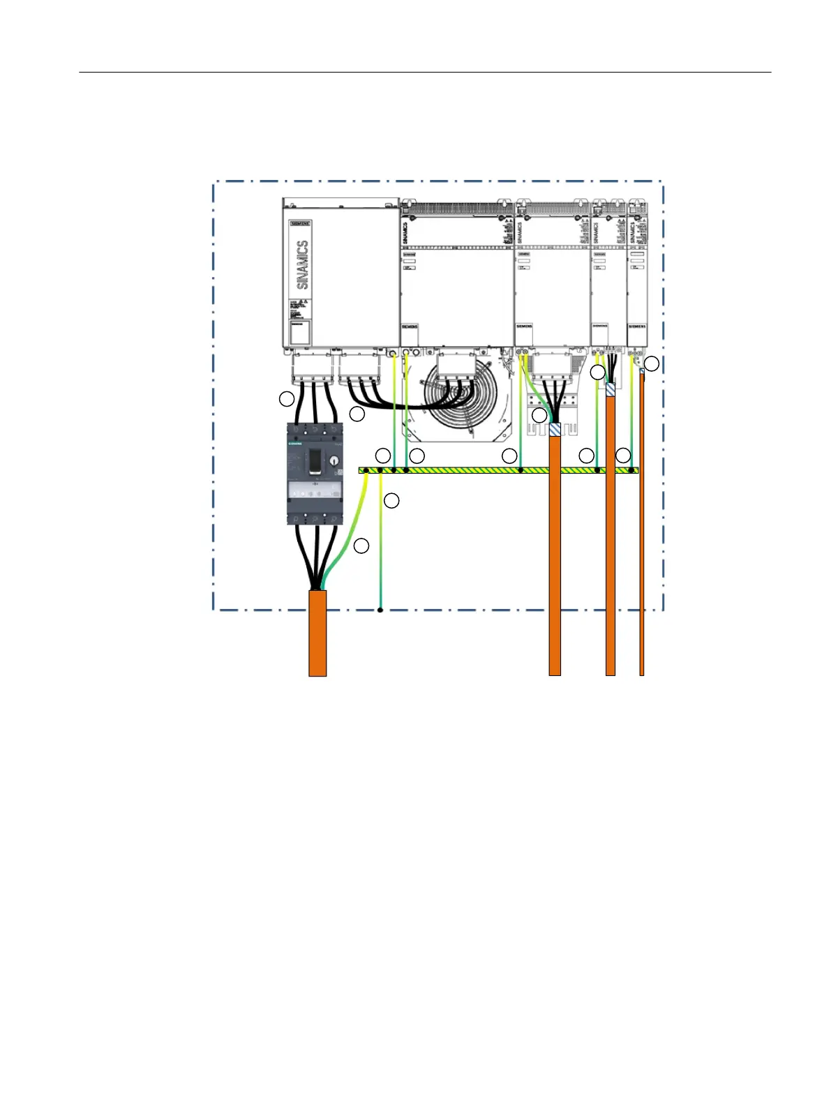
Overview diagram
The following diagram shows the protective connection concept for the drive line-up.
3(UDLO
2YHUFXUUHQW
SURWHFWLRQ
GHYLFH
&RQWUROFDELQHW
0RWRUFDEOHV/LQHVXSSO\
FDEOH
$FWLYH/LQH0RGXOH$FWLYH,QWHUIDFH0RGXOH0RWRU0RGXOHV
① The protective conductor (PE) must be dimensioned in compliance with local installation rules for
equipment with increased leakage currents. As a minimum, it must satisfy one of the following
conditions:
• The protective conductor is routed so that along its complete length it is protected against
mechanical damage.
• The protective conductor has a cross-section ≥10mm
2
Cu.
• A second protective conductor with the same cross-section is provided.
• When establishing the connection using an industrial plug connector according to EN 60309,
as core of a multi-core cable it has a cross-section ≥2.5mm
2
Cu.
• As a core of a multi-core cable, the protective conductor has a cross-section ≥2.5mm
2
Cu.
② The cable cross-section must be dimensioned in compliance with local installation rules.
③ The cable cross-sections must be dimensioned in compliance with local installation regulations.
④ The protective conductor must have the same cross-section as the line conductor of the motor
connection cable.
Application planning
4.15Protective connection and function equipotential bonding
Booksize power units
Equipment Manual, 09/2023, A5E53307519B AA 71
 Loading...


