Description
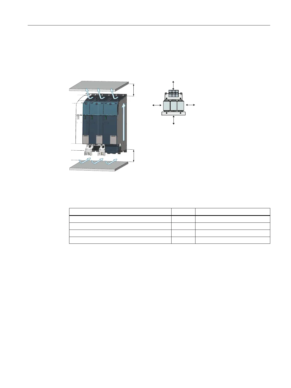
The ventilation clearances are dened by the minimum clearances of the components in the
control cabinet that must be maintained. To ensure adequate ventilation in the control cabinet,
the ventilation clearances as well as the ventilation slots of the components must be kept free
and unobstructed.
Minimum clearances
The following table lists the minimum clearances of the components in the control cabinet.
Table 5-1 Ventilation clearances
Component Unit Minimum clearances A
Smart Line Modules mm 80
1)
Motor Modules mm 80
1)
Line reactors mm 100
2)
Motor reactors mm 100
2)
1)
Minimum clearance A refers to a Motor Module without shield connection plate.
2)
Ventilation clearances around the outside of line reactors or motor reactors with respect to the
mounting surface.
Mounting
5.1Installation in the control cabinet
Booksize power units
Equipment Manual, 09/2023, A5E53307519B AA 77
 Loading...


