Procedure
Proceed as follows to calculate the current load of the DC link busbars:
1. Add the DC link currents I
DC link
of the connected Motor Modules. The DC link current values
are listed in the technical data of the Motor Modules.
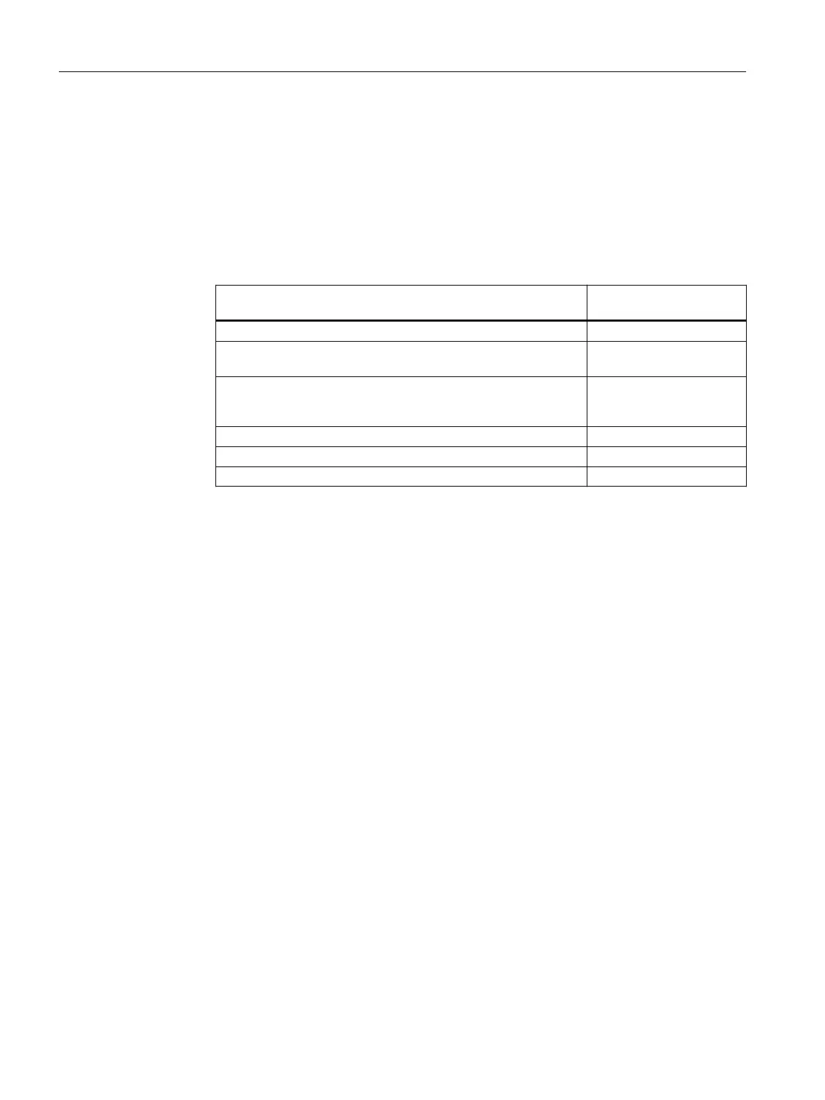
2. Check whether the continuous current-carrying capacity of the DC link busbars is exceeded.
– The maximum current-carrying capacity of the DC link busbars dier for the various
components. You can take the values from the following table:
DC link busbar or bridge Continuous current-carry‐
ing capacity [A]
1)
Smart Line Modules 100mm 200
Motor Modules 50mm
with 4mm DC link bridges
100
Motor Modules 50mm
with 6mm DC link bridges
(Article No. 6SL3162-2BB00-0AA0)
200
Motor Modules 100mm 200
Motor Modules 150mm - 200mm 250
DC link components 100
1)
The continuous current-carrying capacity specied here applies to an ambient temperature of
up to 40°C. From
40°C to 55°C, the continuous current-carrying capacity is reduced by 2.67% per °C.
For the planned conguration, if the current load to be assumed exceeds the continuous
current-carrying capacity of the DC link busbars, then the following solution is available to
congure the drive line-up:
• Center infeed: Conguration with infeed at the center and the Motor Modules and DC link
components mounted to the left and right
Mounting
5.2Layout of the components
Booksize power units
80 Equipment Manual, 09/2023, A5E53307519B AA
 Loading...


