Programming technological functions (cycles)
8.2 Milling
Milling
Operating Manual, 03/2010, 6FC5398-7CP20-1BA0
307
Parameter Description Unit
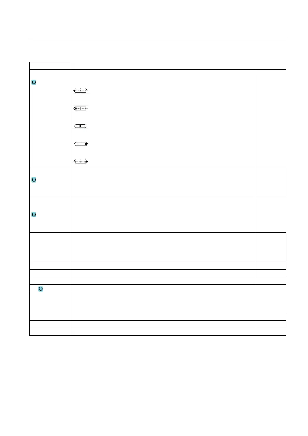
Reference point
Position of the reference point:
(lefthand edge)
(inside left)
(center)
(inside right)
(righthand edge)
Machining
∇ (roughing)
∇∇∇ (finishing)
∇∇∇ edge (edge finishing)
Chamfering
Machining
position
Single position
A slot is milled at the programmed position (X0, Y0, Z0).
Position pattern
Several slots are milled at the programmed position pattern (e.g. pitch circle, grid,
line).
X0
Y0
Z0
The positions refer to the reference point:
Reference point X – (for single position only)
Reference point Y – (for single position only)
Reference point Z
mm
mm
mm
W Groove width mm
L Groove length mm
α0 Angle of rotation Degrees
Z1 Slot depth (abs) or depth relative to Z0 (inc) – (only for ∇, ∇∇∇ and ∇∇∇ edge) mm
DXY
Maximum plane infeed
Maximum plane infeed as a percentage of the milling cutter diameter
- (only for ∇ and ∇∇∇)
mm
%
DZ Maximum depth infeed - (only for ∇, ∇∇∇ and ∇∇∇ Rand) mm
UXY Plane finishing allowance - (only for ∇, ∇∇∇ and ∇∇∇ edge) mm
UZ Depth finishing allowance (slot base) - (only for ∇ and ∇∇∇) mm

 Loading...


