Programming technological functions (cycles)
8.6 Further cycles and functions
Milling
Operating Manual, 03/2010, 6FC5398-7CP20-1BA0
411
● Machine manufacturer has set the direction reference to rotary axis 1 (B) when he
commissioned the swivel function.
● A rotation around X (WCS) of 10 degrees is programmed in the swivel cycle.
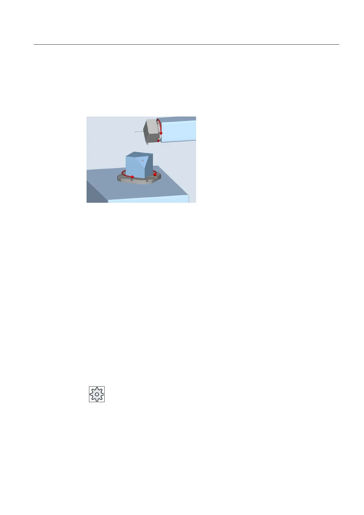
The machine in the basic setting (pole setting) of the kinematics (B = 0 C = 0) is shown in the
following diagram.
● Direction "-" (minus)
– Rotary axis B moves to -10 degrees in the negative direction (red arrow).
– Rotary axis C moves to 90 degrees (rotation around X!).
● Direction "+" (plus)
– Rotary axis B moves to +10 degrees in the positive direction (red arrow).
– Rotary axis C moves to 270 degrees.
The two "Minus" or "Plus" direction settings enable a workpiece to be machined with
swiveled planes. The two solutions calculated by the NC differ by 180 degrees (see rotary
axis C).
Tool
To avoid collisions, you can use the 5-axis transformation (software option) to define the
position of the tool tip during swiveling.
● Correct
The position of the tool tip is corrected during swiveling (tracking function).
● No correction
The position of the tool tip is not corrected during swiveling.
Machine manufacturer
Please refer to the machine manufacturer's specifications.

 Loading...


