VA Motion Controller Programming Manual
436
Value of 0 to 7
corresponding to the input
point I0.0 ~ I0.7,8 ~ 15
corresponding to the input
I1.0 ~ I1.7
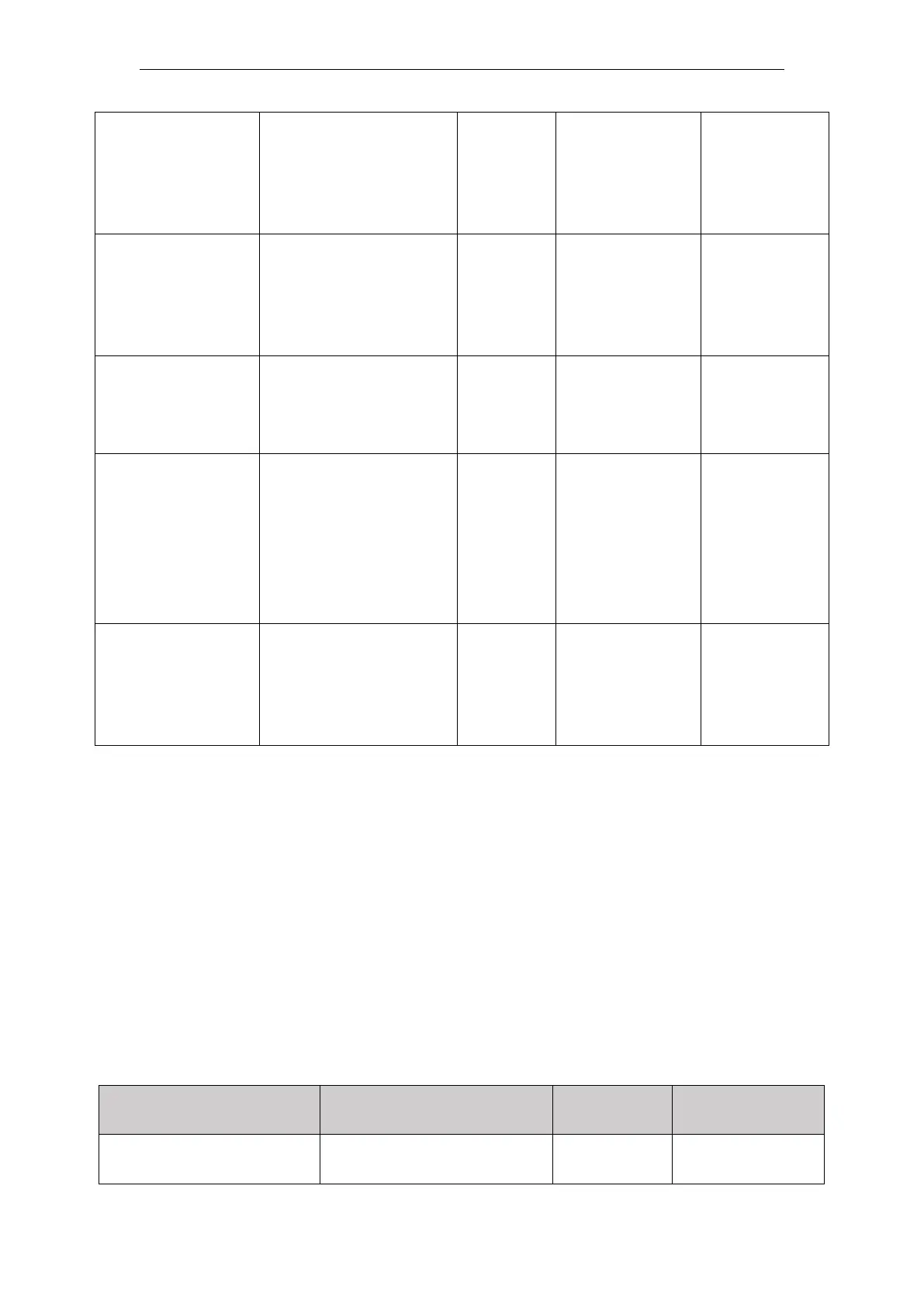
Mark_DI_Edge
(Color signal
edge punctuation)
Punctuation set color
signal trigger edge
along
0: Falling
1: Rising
Exexcute
from FALSE to
TRUE
Cut_DI_Valid
(Cut point signal
valid bit)
Status is TRUE
effective cut point signal;
FALSE cutting point signal
is invalid;
Exexcute
from FALSE to
TRUE
Cut_DI_Num
(Cut point signal)
Cutting bit number
designated terminal, the
input value of 0 to 7
corresponding to the input
point I0.0 ~ I0.7,8 ~ 15
corresponding to the input
I1.0 ~ I1.7
Exexcute
from FALSE to
TRUE
Cut_DI_Edge
(Cutting edge
point signal)
Cutting edge set-point
signal trigger
along
0: Falling
1: Rising
Exexcute
from FALSE to
TRUE
Description:
For Disc_Circumference peeling axis and the feed axis, set FeedAxisRadius (feed shaft
radius), RotaryAxisRadius (peeling axis radius) before, should their respective axis parameter
module MC_AXIS_REF, set their respective radii match (circle circumference of the disc)
parameters for use in MC_ReadActualPosition, MC_ReadActualVelocity module.
When the instruction is being executed may be modified CutLength, after re-trigger value
Execute SyncAngle, FeedAxisRadius, RotaryAxisRaidus, RotaryAxisKnifeNum,
First_Mark_Offset, Mark_DI_Valid, Cut_DI_Valid, the modified parameters to take effect in
the next cycle after the trigger cam Execute. Execute and do not re-trigger CommandAborted
set to TRUE;
The CANopen mode, or the tangent point with color function is not available.
Output parameters
InSync (synchronized
state)
This parameter is TRUE
output shaft from the
 Loading...
