VA Motion Controller Programming Manual
562
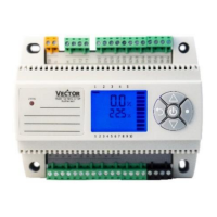
Figure above, center coordinates I = X1 + Param_I, J = Y1 + Param_J, K
= Z1
End point coordinates X = Pos_Dis_X, Y = Pos_Dis_Y, Z = Pos_Dis_Z.
CirMode = 1,
Param_R = 0
Param_I = A, A ≠ 0
Param_K = B, B ≠ 0
Param_J = 0
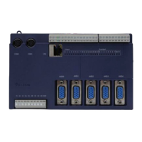
Method ZX plane center circle. When using this method, Param_I
representative of the center position with respect to the X axis offset of the
starting position, Param_K representative of the center position with respect
to the Z-axis offset of the starting position.
Figure above, center coordinates I = X1 + Param_I, J = Y1, K = Z1 +
Param_K,
End point coordinates X = Pos_Dis_X, Y = Pos_Dis_Y, Z = Pos_Dis_Z.
CirMode = 2,
Param_R = 0
Param_J = A, A ≠ 0
Param_K = B, B ≠ 0
Method YZ plane center circle. When using this method, Param_J
representative of the center position with respect to the Y-axis offset of the
starting position, Param_K representative of the center position in the Z-axis
offset relative to the start position.