3. Configuration
For this system, M and N are defined as follows:
•Misdefined as the number of input frames of data (defined by input vertical sync) that are required to
constitute a full frame of image data. This parameter is used to determine the “base” or “full” image
frame rate for the input data, in the form: Base rate (Hz) = Input frame rate (Hz) / M.
•Nisdefined as the number of frames of data to be displayed during a base rate time. This parameter
is used to determine the output vertical rate, in the form: Output rate (Hz) = Base rate (Hz) * N
The following are a few examples:
Example 1:
• Full frame of picture data input each vsync, therefore M = 1
• One frame of picture data output each base rate, therefore N = 1
E.g. 24 Hz input, 24 Hz output (Normal projector use)
Example 2:
• ½ frame of picture data input each vsync, therefore M = 2
• frames of picture data output each base rate, therefore N = 4
E.g. LR data input at 48Hz, LRLR output at 96Hz (LRLR 3D)
6:2 is generally used for 3D.
FramerateSetup
TiponthecomboboxnexttoMultiplication and select the desired multiplication.
1:1 is normal projector use.
6:2 is generally used for 3D
others are used for experimental purposes.
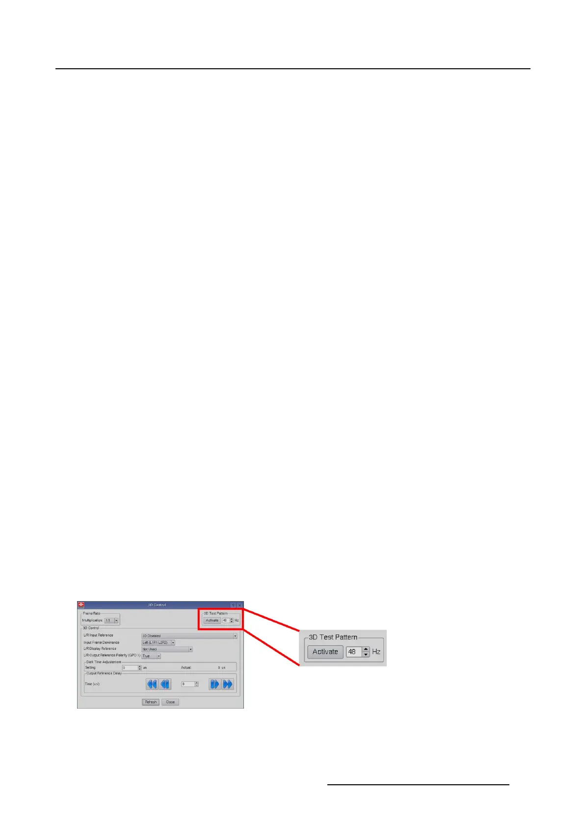
3.7.2.4 3D Test pattern
What can be done?
With the 3D test pattern, it is possible to test the complete setup in combination with an external polarizer
system, or active polarity glasses. The output frequency of the test pattern can be entered so that the
simulation of the input signal is completely.
Entering the output frequency
1. Tip in the input field next to Activate. (image 3-39)
2. Enter the new frequency with the keyboard.
Or,
tip on the up down control of the spin box until the desired frequency is reached.
Image 3-39
3D test pattern
R59770488 COMMUNICATOR TOUCH PANEL 06/06/2012 69
 Loading...