117Service Manual – CS7010™ 24 - Electrical System
7. Slide the battery tray out until it reaches the
end of the tether cable.
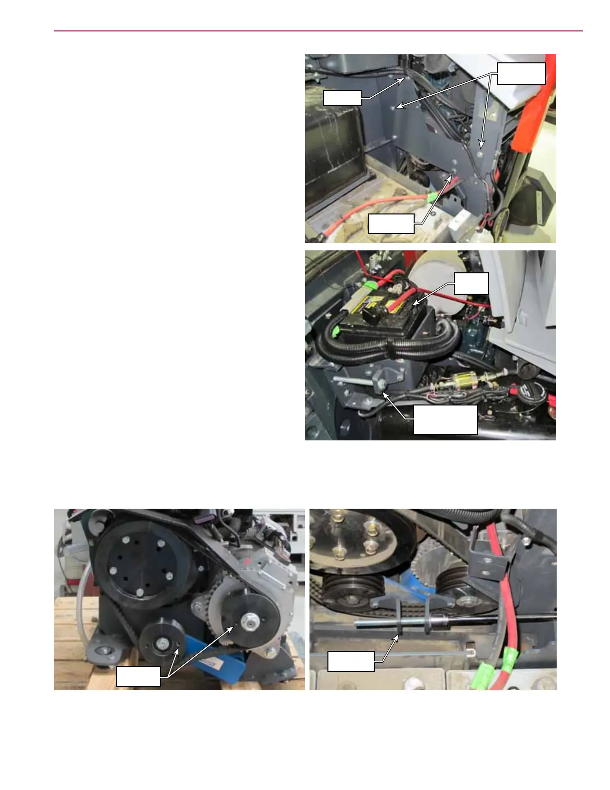
8. Remove the two screws that secure the belt
guard to the back of the tank guard plate.
9. Remove the P-Clamp, cable, and fuel lines from
the top of the tank guard plate.
10. Remove the 5 screws that secure the tank guard
plate to the frame, and remove the plate.
11. A belt de-tensioning tool is stored on the side of
the engine battery box. Remove the two screws
securing it to the box and remove the tool from
storage.
12. Unscrew the adjustment screw on the tension
tool until the two halves are far enough apart to
reach the mounting holes in the generator pulley
and idler pulley.
13. Using the screws that previously attached the
tool to the battery box, bolt the de-tensioning
tool across the two pulleys.
14. Begin tightening the adjustment screw to draw
the idler pulley toward the generator pulley until
enough tension has been removed from the belt
to remove it.
15. Replace the belt and reassemble the machine. Make sure to replace the de-tension tool in its storage
location.
Belt Guard
Screws
Tank Guard
Screws (5)
P-Clamp
Belt De-Tension
Tool Storage
location
Engine
Battery
Mounting
Holes
De-tension
Tool