75Service Manual – CS7010™ 14 - Wheel System, Non-Traction
Brake and Spindle Assembly
WARNING: Never work under a machine without safety stands or blocks to support the machine.
When jacking the machine, do so at the designated tie down/jacking locations.
1. Jack the front of the machine enough
to raise the front wheels slightly off the
ground, and place jack stands under the
machine for safety.
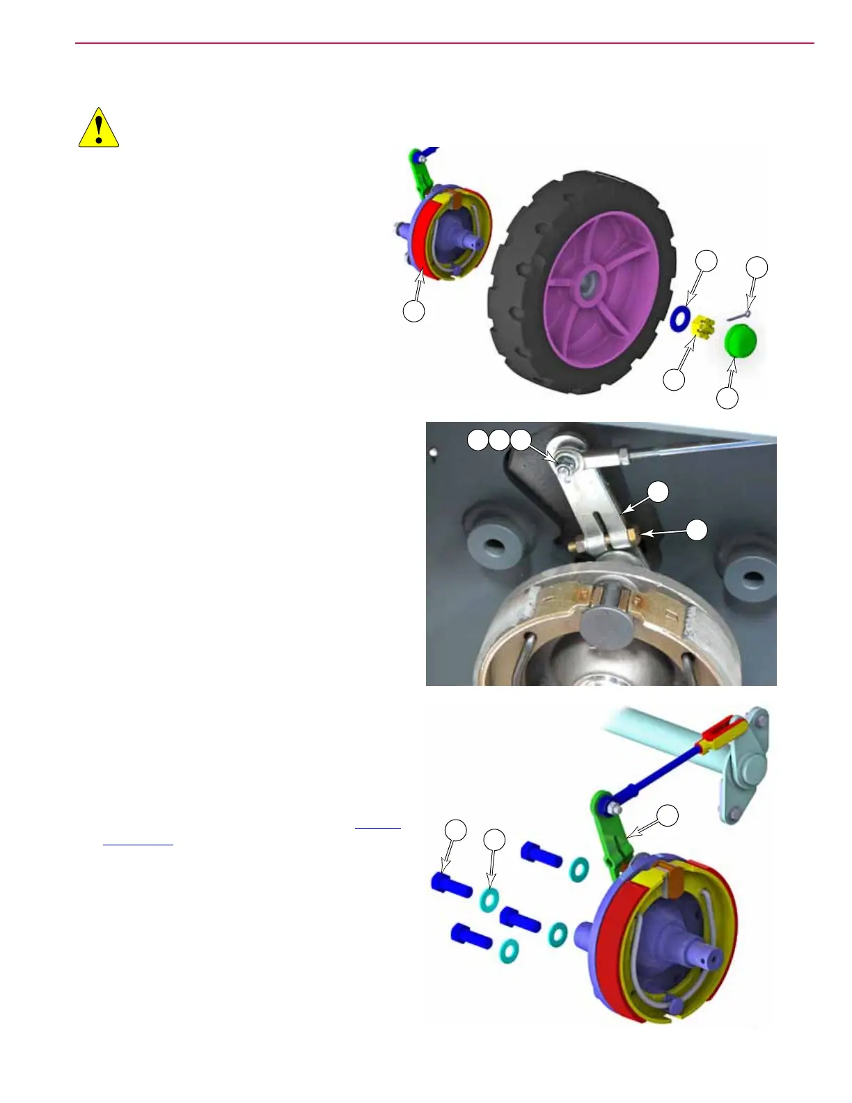
2. Using a sharp-edged tool, carefully work
the dust cap (A) loose from the wheel. Take
care not to damage or deform the cap.
3. Remove the cotter pin (B) from the castle
nut (C), and remove the nut, washer (D),
and wheel from the axle spindle (K).
4. Remove the nut (K), 2 washers (L), and
bolt (M) that secure the brake linkage to the
brake actuator arm (N), and remove the linkage.
5. Remove the four bolts (P) and washers (Q) that
secure the brake assembly to the machine frame,
and remove the assembly.
6. Compare the old and new brake assembly to
ensure that the brake actuator lever (N) is in the
same position. If not, loosen the clamping screw
(O), remove the lever from the splined shaft, and
reinstall it in the correct angular position.
7. Install the new spindle assembly.
8. Before reinstalling the wheel, inspect the drum
surface for wear, and the wheel bearing for
proper movement.
9. After replacing both brake assemblies, Adjust
the Brakes described on page 73.
A
B
C
D
H
MK L
O
N
N
Q
P