68Service Manual – CS7010™ 04 - Control System
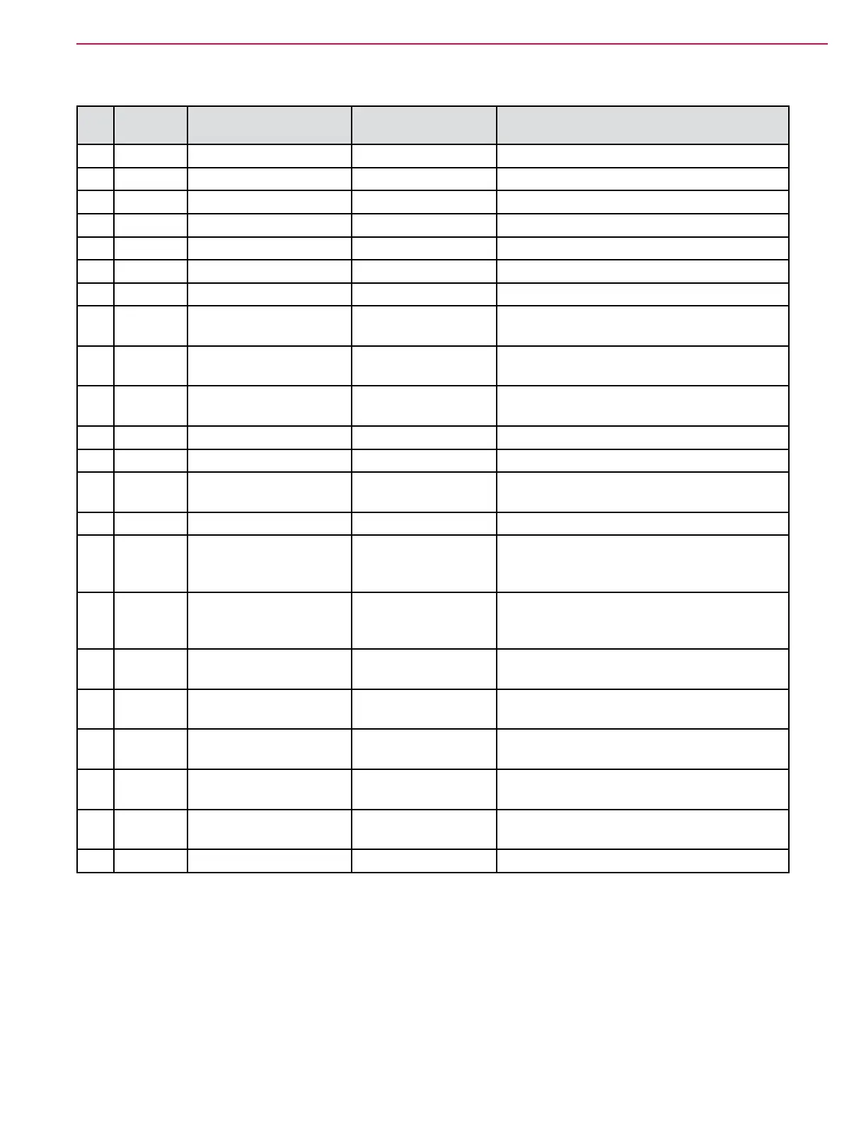
J2 Connector
J2
Pin
Wire Circuit Description Value/Condition Comments
1 YEL-BRN CAN 0 High 2.79 V
2 GRN
CAN0Low 2.30 V
3 BLK
BatteryNegativePower 0.001 V
4 BLU-BLK Sensor Ground 0.001 V
5
6 BLK
BatteryNegativePower 0.001 V
7 GRY-GRN 3.3V sensor supply 2.89 V
8 WHT-GRN Dust Control Filter 4.7 V open
0.001 V closed
(Closeswhenlterisdirty)
9 ORN-GRY BrakeSwitchinput 5.7 V open
0.001 V closed
(Closeswhenpedalisatrest)
10 GRY-YEL Extended Scrub Level 5.1 V open
0.001 V closed
(ClosesWhentankisempty)
11 GRN-WHT CAN1Low 2.53 V
12 YEL/WHT CAN 1 High 2.61 V
13 GRY-VIO
HopperInterlock 5.7 V open
0.001 V closed
(Closeswhenhopperisdown)
14 YEL-VIO HopperFireSwitch 4.9 V open (Closes at 140 degrees F.)
15 GRN-YEL Coolant Temp input 4.7 V
ECUoutput3.Theinputisactive-low,and
willbepulledtogroundforanover-temp
condition
16 YEL-RED
OilPressureinput 5.2 V Engine off or
running
ECUoutput2(LEVengineonly).Active-low
inputwhichwillbepulledtogroundiftheoil
pressureislowwhiletheengineisrunning.
17 ORN-RED Dump Door Position 0.91 V door closed
0.19 V door open
Analog input from actuator
18 GRN-ORN Dump Door Closed 4.9 V open
0.001 V closed
(Closeswhendoorisclosed)
20 TAN-RED MILinput 12.2VnoMIL
0.03VMIL
MalfunctionIndicatorLamp,
a.k.a.Checkenginelight
21 BLK-YEL 12V output for exterior
lamps
12.01 V
22 TAN-RED Main Broom Position
Sensor
2.50 V up
1.23Vdown
Analog input from actuator
23 TAN-WHT Fuel Level input 3.28 V
LPGwithpressure