98Service Manual – CS7010™ 24 - Electrical System
Circuit Protection
There are several layers of circuit protection. The top level protection is the 400-amp fuse from the main
battery pack. The second level protection is the circuit breakers in the operator’s platform. This includes the
5-amp circuit breaker to the main controller, the 25-amp breaker to loads on the main controller, and a 25-
amp breaker to the steering system. Each of the secondary controllers and power modules contain their own
internal overload protection for their respective loads.
Un-Switched Power
Some devices receive power even when the machine is not in operation. The only way to disable power
to these devices and circuits is to disconnect the main battery connector. The main control board always
receives logic power, because it needs to detect the ignition key sequence to start the engine and also
initiate power to other subsystems. Even though the main power relays are not active until their respective
controllers are active, the relays are always receiving unswitched power to their contacts.
Switched Power
The ignition switch doesn’t really carry any machine power function, but it noties the main controller that
the key has been operated and the machine should begin operation. The main controller then activates the
K1 relay, which provides operational power to the rest of the system. Each of the secondary controllers and
power modules receive their main logic power through the K1 relay.
Prime Power Alternator (Generator)
The 42 volt generator provides the electrical power needed to operate the machine and to recharge the 36
volt battery pack. It is belt driven by a pulley located at the rear of the engine (Right side of machine). The
alternator contains an external voltage regulator to provide sufcient voltage to the main battery pack to
charge the batteries.
Lighting
All headlights, curb light, taillights and turn lights are controlled by the main machine controller. Head
lights are standard. The curb light and turn lights are optional See the Options and Accessories chapter for
more information on curb lights and turn lights.
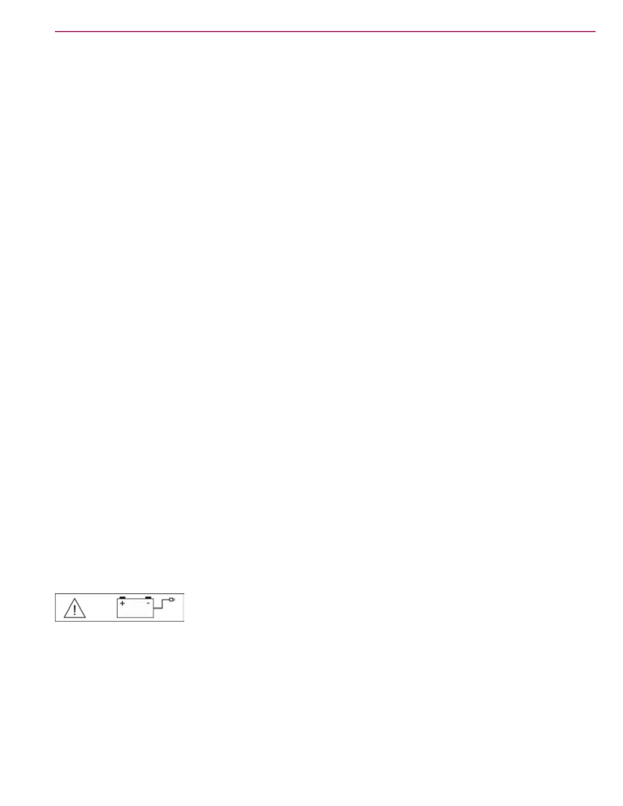
Low Voltage Cutout
The scrub system and solution system are cut off by the main machine controller if the system voltage falls
too low (Approx 31.5v for “wet” batteries or 32.94v for gel batteries). This is done to prevent damaging the
batteries from over discharging. The operator will see the low voltage warning icon displayed when the low
voltage cut out mode is active
There are actually two levels of low voltage cut off. The rst level disables the scrub and sweeping functions.
The second level will also disable the recovery function. In either case, the hopper functions are not disabled.
Once the machine has gone into the low voltage cut out mode, the batteries must be fully recharged before
normal operation is restored (Approx 38.7v) .