96Service Manual – CS7010™ 22 - Steering System
Specications
Shop Measurements
Shop measurements are values that were measured on a real machine. While they are not “specications”,
they can help you recognize normal vs. abnormal. All voltages are DC unless otherwise stated and were
measured with the negative (black) voltmeter lead on battery negative and the key on.
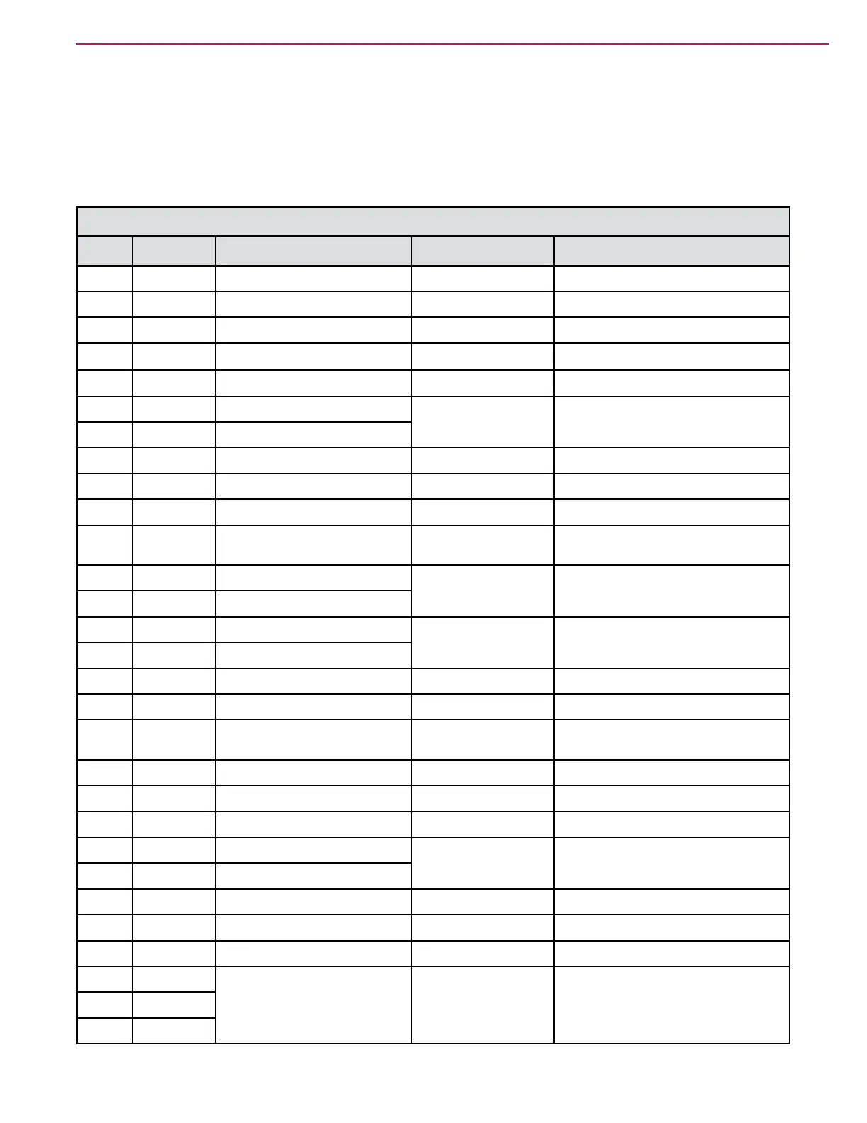
Steering Controller Measurements
Pin # Wire Color Circuit Voltage Comments
J6-1
VIO-WHT
TFD coil (positive) 37.9 V Unswitchedside
J6-3
ORN-GRN
KSI(KeySwitchInput) 38.2 V
J6-4
ORN-GRN
Enable Drive output 0.001 V Activelowwhensteeringready
J6-5
RED-BLU
12Vpowertoresolver 10.94 V
J6-6
BLK
Internalsensorground 0.002 V
J6-7
VIO-GRY
Encoder 1A input
1.2 - 3.7 V, variable
Analog resolver signal for motor
rotor position
J6-8
WHT-GRY
Encoder 1B input
J6-10
BLK
Batt-ControlPower 0.001 V
J6-11
BLK
Batt-tosteeringwheelsensor 0.002 V
J6-13
YEL-BLK
K5 Relay Coil 7.85 V PWM to Batt-
J6-15
ORN-RED
SW12 Right Travel limit
switch
38.2Vblocked
Sensorwillonlybeblocked
momentarily in normal operation
J6-16
GRN-WHT
TFD encoder 1
0.40 - 4.59 V
Analog voltage from sensor that
rampsup/downwithposition
J6-17
GRN-BLK
TFD encoder 2
J6-18
VIO-PNK
Encoder 3A input
1.2-3.7 V variable
Analog resolver signal for motor
rotor position
J6-19
WHT-PNK
Encoder 3B input
J6-21
GRN
CAN0Low 2.3 V
J6-23
RED-GRN
5VpowerforTFDencoders 4.97 V
J6-24
BRN-GRN
TFD coil (negative)
"34.7 V "normal feel"
28.2 V at limit stop
PWM to ground
J6-26
PINK
Steering Actuator temperature 1.11 V at 22 Deg. C.
J6-27
ORN-BLU
SW11LeftTravellimitswitch 38.5 V momentary
J6-29
YEL-BLU
K5 relay coil 38.6 V UnswitchedBatt+
J6-30
GRN-WHT
TFD encoder 1
0.40 - 4.59 V
Analog voltage from sensor that
rampsup/downwithposition
J6-31
GRN-BLK
TFD encoder 2
J6-33
YEL
CAN 0 High 2.78 V
Lug B-
BLK
Battery Negative 0.001 V Mainpower
LugB+
GRY-WHT
Battery Postive 38.49 V Mainpower
Lug U
BRN
M26 Steering Actuator Motor
phase output
PWM vector sinusoidal simulationLug V
RED
Lug W
WHT