227Service Manual – CS7010™ 34 - Scrub System
Circuit Description
Scrub functions are driven by the Main Machine Controller via Power Module #2 using CAN Bus commands.
The Power Module receives its control power (turn-on power) via the KSI (Keyswitch) input. The power
module controls its own main power by energizing the K3 relay. This provides both internal positive high-
power, as well as external positive power to the brush motors.
The power module controls the brush motors by switching the output to ground. The amperage through the
motor is monitored by the power module. The deck lift actuator is controlled by a reversible PWM output.
The actuator contains internal limit switches to control travel, and will be described in more detail below.
Scrub Deck Actuator Motor
The PWM Outputs from Power Module #2 provide voltage to the Scrub Deck Actuator Motor. The output
polarity determines whether the Scrub Deck Actuator lowers or raises the scrub deck.
The top of the actuator gearbox contains a pair of limit switches that are activated by cams driven from
the motor. These limit switches have diodes in parallel, which effectively turns the switch into a polarized
switch. Each switch functions only when the input polarity opposes the direction of the respective diode.
The signicance of this is that the retraction limit switch, for example, will open the circuit when the motor
reaches the upper retracted limit, but will still keep the circuit closed if the polarity is reversed to extend the
actuator.
The power module monitors the brush motor amperage and reports this back to the Main Controller. The
Main Controller uses this information to increase or decrease scrub deck pressure by raising or lowering the
actuator to achieve the target amperage.
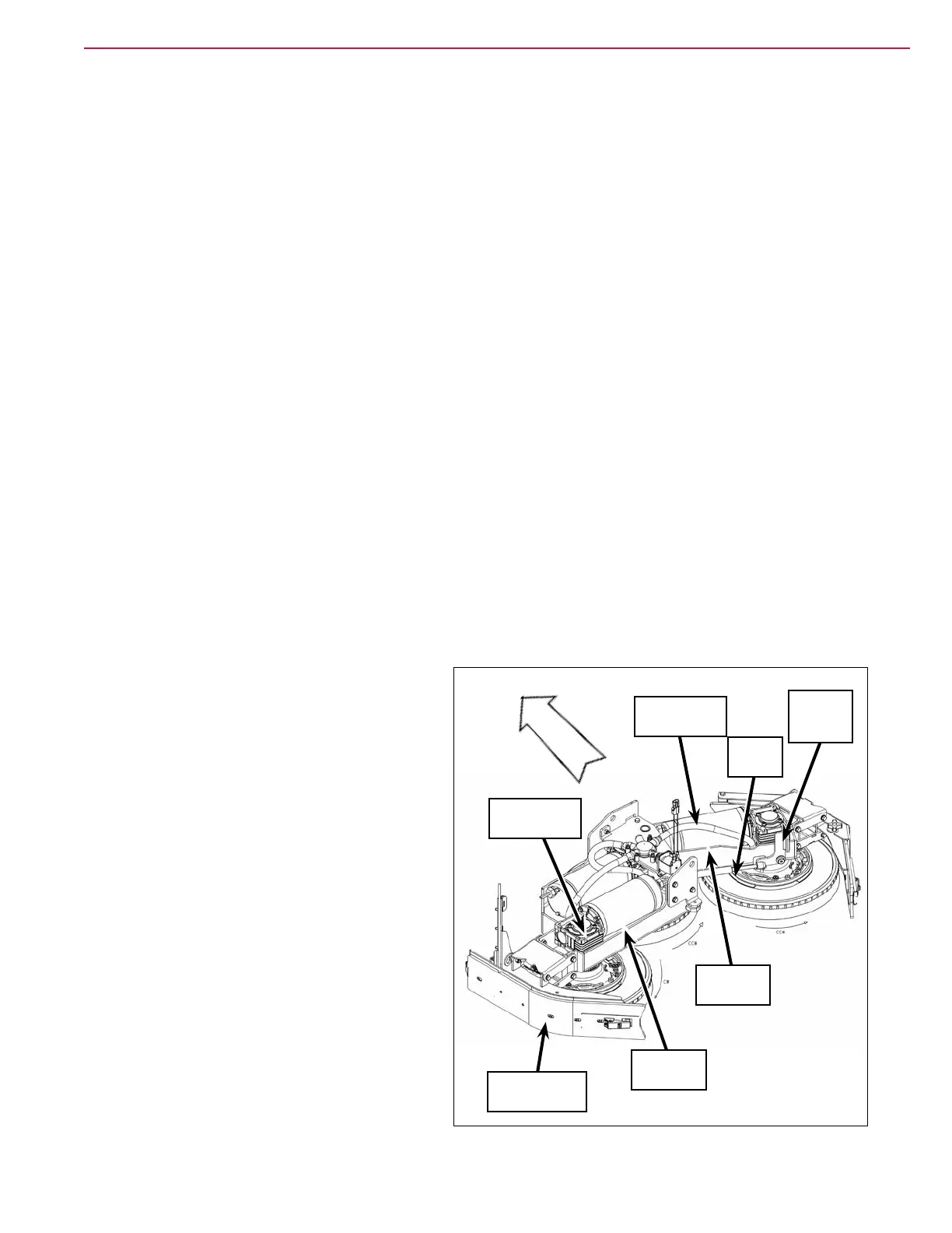
Component Locations
Scrub Motor Assemblies
The left-hand and center scrub motor assemblies
are mounted on the main deck platform. The
right-hand scrub motor is mounted on a swingarm
platform. The right-angle gearboxes are mounted
on spacers to position them correctly on the deck
and swingarm platforms.
Right Swingarm
A gas spring keeps the right swingarm and
attached side squeegee assembly extended
outward during normal scrubbing, but will allow
the swingarm to pivot backward if the right-hand
side squeegee hits an object or obstacle. This
provides some compliance to prevent damage to
the side squeegee assembly.
To release the gas spring to pivot the right
swingarm backward for service or maintenance
proposes, pull the top of the lever arm toward you
and swing the swingarm backward.
Scrub Motor
Assembly (3)
Arm
Weldment
Side Squeegee
Assembly (2)
Right-angle
Gearbox (3)
Deck
Weldment
Front
Gas
Spring
Lever Arm
Bracket