259Service Manual – CS7010™ 42 - Sweep System, Main
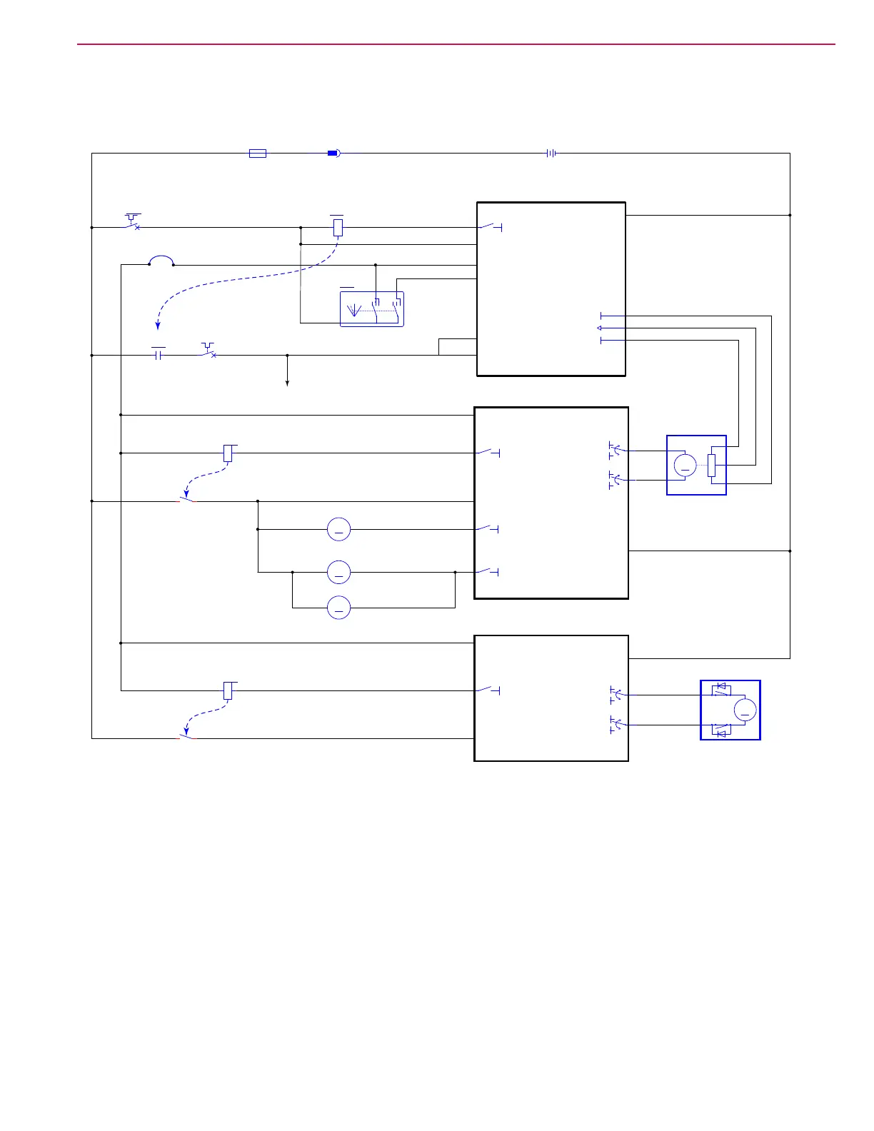
Sweep System Wiring Diagram
The diagram below contains both main broom and side broom circuitry.
B-
BLK
A1
MAIN MACHINE
CONTROLLER
J1-19
J1-6
J1-30
VACC2
VACC1
VACC2
J1-29
TO 1A3, 1D2
RED BLK
BLK-ORN
YEL-BRN
YEL-BRN
RED
RED
VIO
B-
BT1
BATTERY, 36VDC
+
-
X166
K1b
MAIN RELAY
1
2
X169
K1a
MAIN RELAY
CB1
IGNITION SW 5 AMP
1 2
CB2
VACC2 25 AMP
1 2
F1
FUSE, 400 A.
1
2
START
KSI Input
J1-21
VIO-GRN
ORN
ORN
fiflfl
fi
SW1
SWITCH, IGN.
BAT
ON
ST
Telematics
Jumper
VIO-BLU
BRN-WHT
B-
B+
M
+
_
B-
B+
J2-4
J2-22
J2-7
GRY-GRN
TAN-RED
BLU-BLK
+3.3V
B-
M1
WHT-VIO
BLU-GRY
M
M1
MOTOR, MAIN BROOM
-
+
B-
J3-14
J3-13
M
M6
MAIN BROOM ACTUATOR
1K OHM
+
_
B-
B+
B-
B+
M3
WHT-BRN
BLK-WHT
BLU-GRY
M
M3R
MOTOR, RIGHT SIDE BROOM
-+
M
M3L
MOTOR, LEFT SIDE BROOM
-+
B-
J4-10
J4-11
M18
SIDE BROOM ACTUATOR
J4-2
A2
POWER MODULE
KSI
B+
B-
J4-9
BRN-GRN
GRN-GRYRED
BLK
ORN
ORN
K2a
COIL, POWER MODULE
3 4
K2b
POWER MODULE
2
1
B-
KSI (Control Power) to Power Module
High Power to Power Module
J4-2
A3
POWER MODULE
KSI
B+
B-
J4-9
TO 3B2
BRN-GRN
GRN-GRYRED
BLK
ORN
ORN
K3a
COIL, POWER MODULE
3 4
K3b
POWER MODULE
2
1
B-
KSI (Control Power) to Power Module
High Power to Power Module
V
ACC2
Power