72Service Manual – CS7010™
14 - Wheel System, Non-Traction
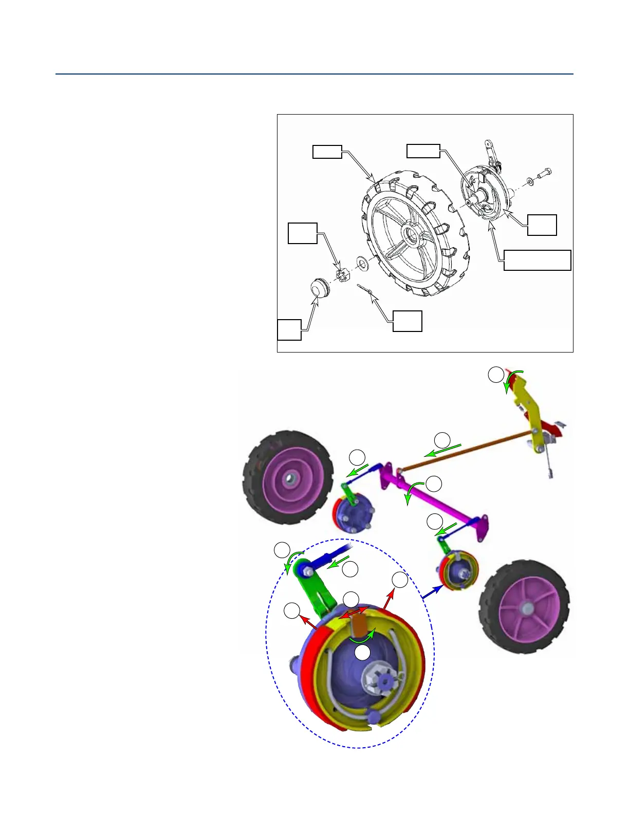
Functional Description
The non-traction wheels support the front
of the machine and house the machine
brakes. The wheel system includes the
Wheels, Brake and Spindle Assemblies
and the various mounting hardware. The
wheels are mounted in the wheel wells on
the front sides of the machine, between
the main broom cover panels and the side
brooms.
The wheels are held onto the spindles
with castle nuts and cotter pins. The
brake and spindle assemblies are fastened
to the machine frame with 1/2”-20 hex
screws.
The braking system is a latching
drum brake, which serves as both the
primary brake, as well as the parking
brake, when latched. The brakes are
actuated with a mechanical link from
the operator’s foot pedal back to the
brake shoes.
When the brake pedal is depressed
(A), the brake rod is moved forward
(B), which causes the brake bar to
rotate (C) about its axis. This in
turn causes the actuator lever (D) to
rotate the brake cam (F).
It is the brake cam that pushes
outward (G) against the brake shoes,
which presses against (H) the inside
of the drum of the wheel.
Wheel
Castle
Nut
Dust
Cap
Cotter
Pin
Brake
Shoes
Spindle
Brake & Spindle
Assembly
A
B
C
D
D
D
E
F
G
H
H