88Service Manual – CS7010™ 22 - Steering System
Commutator Resolver
Commutation is the process of switching power in
the motor windings to coincide with the position
of the magnetic eld of the rotor. A brushed motor
achieves this with mechanical commutation (the
brushes). Remote commutation means that the
motor needs to tell the controller when it should
switch power to the windings, based on the
physical rotational position of the rotor.
Most brushless DC motors accomplish this
information using digital encoders. This results in
the square wave power input. Sinusoidal AC motors/controllers need more precise positional information to
achieve optimal timing. They need analog data. This is provided by a resolver instead of an encoder.
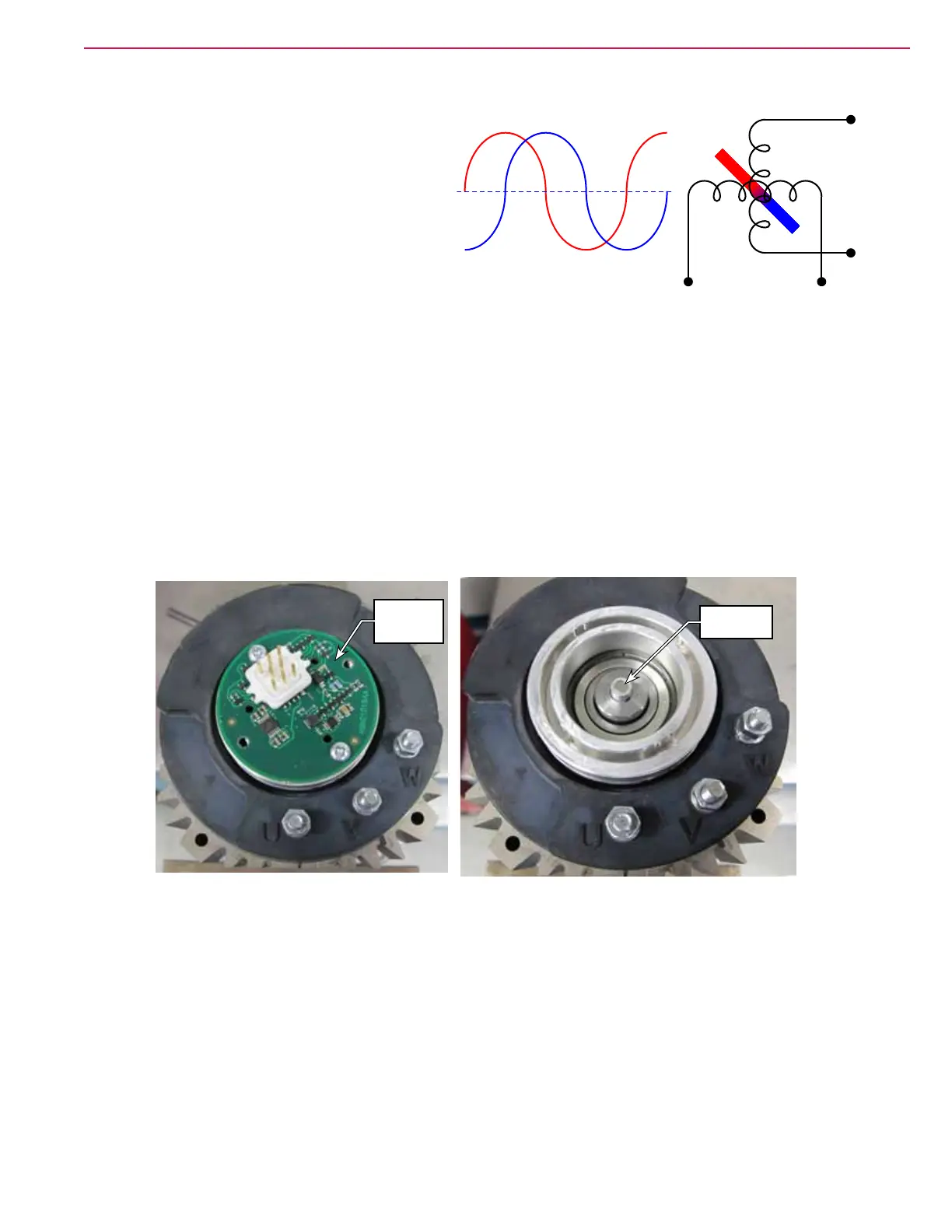
Some resolvers are literally miniature AC generators, while others, including the steering motor, are based
on rotary hall effect sensors, but the effect is the same. The hall effect sensors, or generator coils, are placed
90-electrical-degrees apart above a rotating magnet on the rotor (shown above-right). The resulting output is
a 2-phase sinusoidal signal (shown above-left).
The drive controller mathematically interprets this 2-phase signal to create the commutation points for each
of the three output phases to the motor.
Some resolvers are 3-phase generators, and these do not need mathematical interpretation to create the
commutation points. They are directly matched to the positions of the rotor. The coils are 120-electrical
degrees apart instead of the 90 degrees.
Resolver
Hall Effect
Board
Magnet for
Hall Effect
NS
A
Sin
B
Cos
A
Cos
B
Sin
Cos