226Service Manual – CS7010™
34 - Scrub System
Functional Description
Overview
The scrub system includes the scrub brushes, scrub brush motors, side squeegees, and the scrub deck
actuator which lowers and raises the scrub deck.
The scrub deck actuator lowers the scrub brushes any time the scrub system is enabled. The brush motors
switch on when the drive pedal is moved from the neutral position. The operator can enable the scrub system
independent of the solution and recovery systems to scrub without adding or picking up solution.
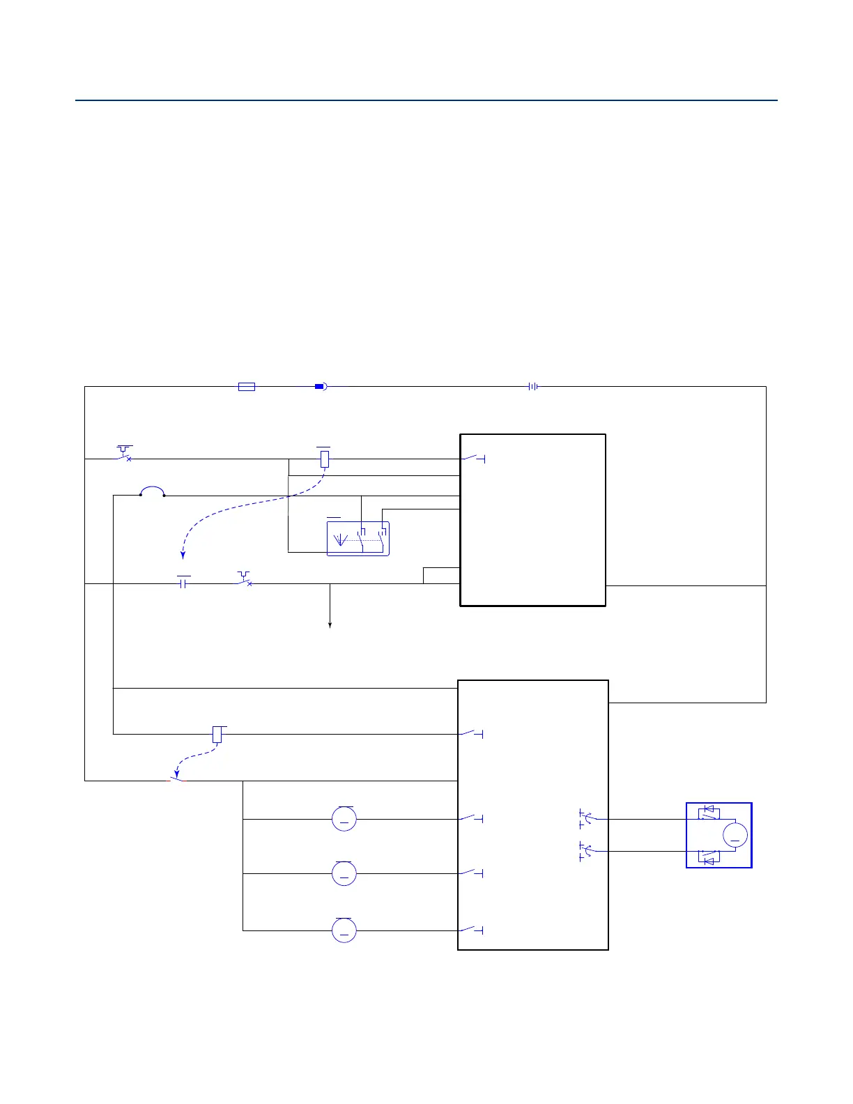
Scrub System Wiring Diagram
B-
BLK
A1
MAIN MACHINE
CONTROLLER
J1-19
J1-6
J1-30
VACC2
VACC1
VACC2
J1-29
TO 1A3, 1D2
RED BLK
BLK-ORN
YEL-BRN
RED
YEL-BRN
RED
RED
VIO
B-
BT1
BATTERY, 36VDC
+
-
X166
K1b
MAIN RELAY
1
2
X169
K1a
MAIN RELAY
CB1
IGNITION SW 5 AMP
1 2
CB2
VACC2 25 AMP
1 2
F1
FUSE, 400 A.
1
2
START
KSI Input
J1-21
VIO-GRN
ORN
ORN
fiflfl
fi
SW1
SWITCH, IGN.
BAT
ON
ST
Telematics
Jumper
VIO
J4-2
M4
M3
M5
J4-6
J4-1
A3
POWER MODULE
KSI
B+
B-
J4-9
TO 3B2
BRN-GRN
GRN-GRYRED
BLK
GRN-VIO
RED-GRY
ORN
BLU-WHT
GRN-GRY
ORN
GRN-GRY
BLU-GRN
GRY-BLK
GRN-GRY
M
M14
MOTOR, LEFT BRUSH DISK
-
+
B-
B+
M
M17
DECK ACTUATOR
+
_
B-
B+
M
M13
MOTOR, CENTER BRUSH DISK
-
+
K3a
COIL, POWER MODULE
3 4
K3b
POWER MODULE
2
1
B-
M
M15
MOTOR, RIGHT BRUSH DISK
-+
B-
B-
B-
KSI (Control Power) to Power Module
High Power to Power Module
V
ACC2
Power