77Service Manual – CS7010™ 20 - Wheel System, Traction
Drive Pedal Potentiometer
The drive pedal potentiometer is a variable resistor connected to the Pin J5--20 input of the drive controller,
with pins J5--31 and J5--32 as reference voltages. As the resistance changes, the drive controller increases or
decreases drive motor speed.
The drive pedal is set up in what’s called a wig-wag conguration, where drive direction is controlled by
a single potentiometer. When the throttle potentiometer is in the center position, the wiper voltage is
approximately 2.8 volts. The speed controller interprets any voltage between 2.3V and 3.3V as neutral
and the output to the motor will be zero. Forward or Reverse movement of the drive pedal rotates the
potentiometer shaft and the wiper voltage is increased for forward travel, or decreased for reverse travel.
The magnitude of the voltage difference away from the neutral point also determines the speed that the
motor will be driven.
To allow for minor variation in the pedal returning to the neutral position, the drive controller establishes
a deadband around the 2.8-volt center. This results in a plus/minus range of voltages where the controller
assumes the pedal is still in the neutral position. The deadband for this drive controller (2.3 to 3.3 V) is set
in the machine’s rmware, and is not adjustable.
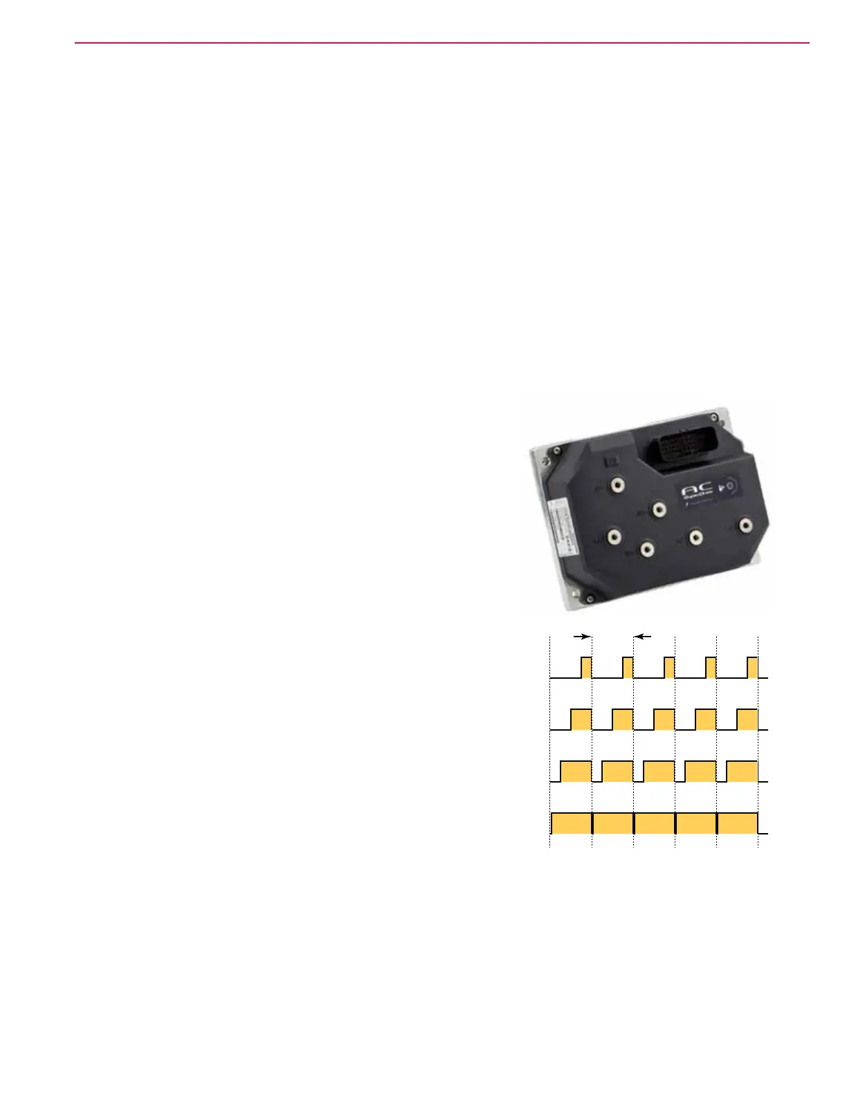
Drive Controller
The drive motor is controlled from an InMotion AC Superdrive
controller, which is an AC induction motor controller for battery
operated equipment. The controller generates a square wave,
3-phase, pulse-width-modulated output to the motor. The speed
controller is designed specically for DC motors with remote
commutation. Pulse-width-modulation (PWM) is a form of motor
speed control that alters the power to a motor by rapidly turning
the power on and off. The ratio (also called “duty cycle”) between the
On and Off states determines how much power the motor receives.
The shorter the “off-time” the closer to full power the motor will
receive. This switching occurs so fast (between 4 and 16kHz for this
controller) that the motor simply sees it as a reduction in power
(voltage) instead of the rapid on/off. PWM is a standard motor
control technique because it is easier to turn power all the way on and all
the way off, than it is to vary the magnitude of the power. Varying the
magnitude would create a lot of heat that would need to be dissipated.
Another unique aspect of the drive controller compared to other PWM
motor controllers in the system, is that the wheel drive motor requires
remote commutation. Mechanical commutation happens with motor
brushes in other motors. For remote commutation, the controller needs
to know what the actual internal rotational position of the rotor is inside
the motor.
The drive motor contains a pair of encoders that tell the drive controller
what the rotational position is of the rotor. The drive controller uses this
information to determine which phase outputs should be energized.
25% PWM Duty Cycle
50% PWM Duty Cycle
75% PWM Duty Cycle
100% PWM Duty Cycle
1-Cycle
(15kHz)