104Service Manual – CS7010™ 24 - Electrical System
Connector Pin-Outs
The following pages contain details about every electrical connector that contains more than one “cavity”.
This is to help you match up the wires and pin numbers of the connector.
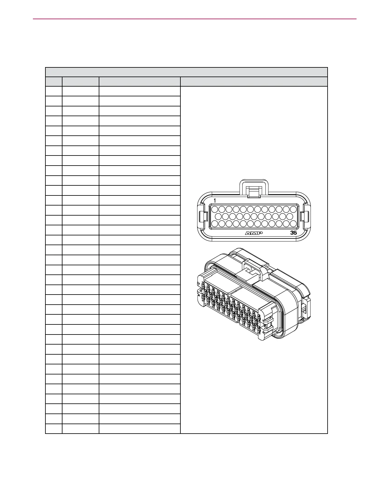
J1 Main Machine Controller
Pin Color Name
1 GRY-BLU Throttle 1
2 GRY-ORN Throttle 2
3 WHT-ORN Hyd. Clutch
4
5 BRN Headlights
6 YEL-BRN VACC1
7 PNK
Ignitionoutput
8 YEL-ORN L2 Solution Valve
9 BLU-PNK Start output
10 GRY-ORN E-Stop input
11 GRN-BLU
BatteryInterlockinput
12 PNK SeatSwitchinput
13 VIO-RED 12VInput
14 WHT-YEL M23 Detergent pump
15 BLU-YEL M23 Detergent pump
16 WHT-RED M24 Detergent pump
17 BLU-RED M24 Detergent pump
18 GRN-BRN
H1BackupAlarm
19 BLK-ORN K1 Main Relay Control
20 YEL-RED LT6 Right Front Turn
21 VIO-GRN
StartInput
22 GRY Run Signal input
23 ORN
KSI(KeySwitchInput)
24 TAN-RED Tail lamp control
25 ORN-YEL LT5 Left Front Turn
26 BRN-RED M1 and L1 Dust Guard
27 BLK
BatteryNegativePower
28 RED-YEL M22 Solution Pump
29 VIO VACC2
30 VIO VACC2
31 ORN-BLU LT9 Left Rear Turn/Stop
32 YEL-GRN LT10 Right Rear Turn/Stop
33 VIO-ORN M19 Extended Scrub Pump
34 BLK
BatteryNegativePower
35 VIO-BRN H2 Horn