78Service Manual – CS7010™ 20 - Wheel System, Traction
Circuit Description
B+
B-
U
V
W
A4
DRIVE CONTROLLER
ENCODER IN 2
ENCODER IN 1
TEMP SENSOR
KSI
SEAT SWITCH(DIN_1)
(C) TO 4B4
(D) TO 6A1
J5-29
J5-4
J5-12
J5-28
J5-5
J5-8
J5-7
J5-6
J5-26
J5-20
J5-32
J5-31
J5-33
J5-21
J5-19
E-STOP(DIN_2)
FOOT PEDAL THROTTLE
J5-17
ENABLE DRIVE
J5-3
(HS_IN)
RED
RED
RED
REDRED
VIO-GRN
TAN-ORN
PNK-RED
TAN-BLK
PNK-BLU
BLK-PNK
TAN-RED
BRN-RED
WHT-BLK
VIO-BLK
YEL
GRN
VIO/WHT
RED
BLK
BLK
ORN-GRN
PNK
ORN
GRY-ORN
B-
B-
RED
RED
FROM 1B3
FROM 1B3
FROM 1B3
CAN0 H
CAN0 L
TO 6B5
+11V
+3V
+5V
B-
+11V
X91
1
2
3 4
B-
M
3~
U
V
W
1 2 3
4
1
2
DRIVE MOTOR
+11V
M9
R4
POT 5K OHM
C
B
A
K4b
WHEEL DRIVE
B+ (HS_OUT)
1
2
3
4
B- (OD_1)
X92
12
12
K4a
WHEEL DRIVE
+11V
+11V
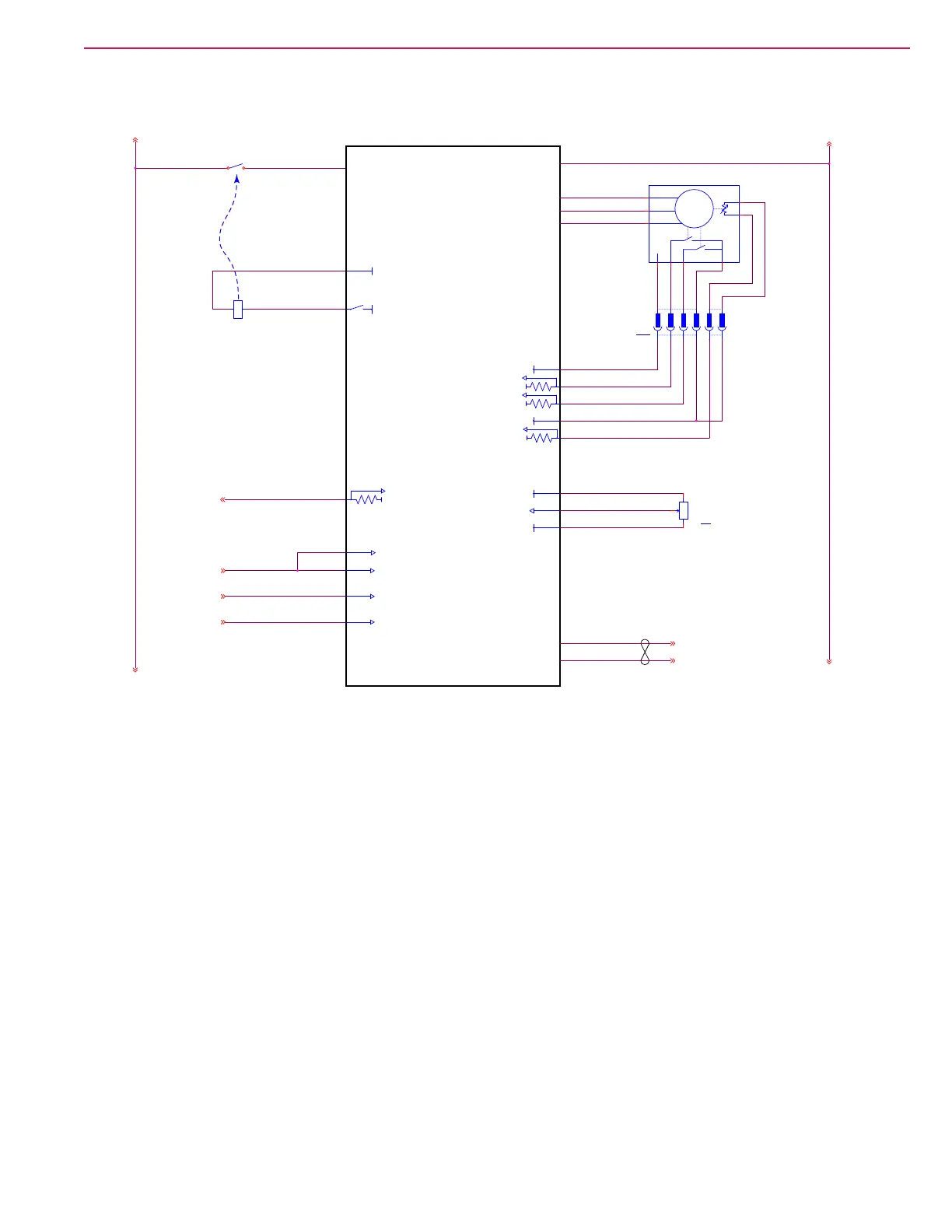
Powering up the Drive Controller
The KSI input is the primary control power for the drive controller. This originates from the keyswitch input
when the vehicle key is in the on position. The drive controller is also enabled/disabled by the interlock and
seat switch inputs. If either of these inputs is open-circuit, the drive controller is disabled. When closed, they
provide positive battery signals to the controller.
When the drive controller is active, it energizes the coil of the K4 relay, which in turn provides high-current
power to the controller for motor output.