278Service Manual – CS7010™ 48 - Sweep System, Side Broom
12. Remove the 1/2”-13 x .75” Hex Screw and
washer and carefully remove the Side
Broom Assembly from the machine.
13. Reinstall the side broom motor assembly
by following the above steps in reverse
order.
Note: Use Loctite® #242 (blue)
on the 1/2”-13 x .75” Hex
Screw when you reinstall
the Screw.
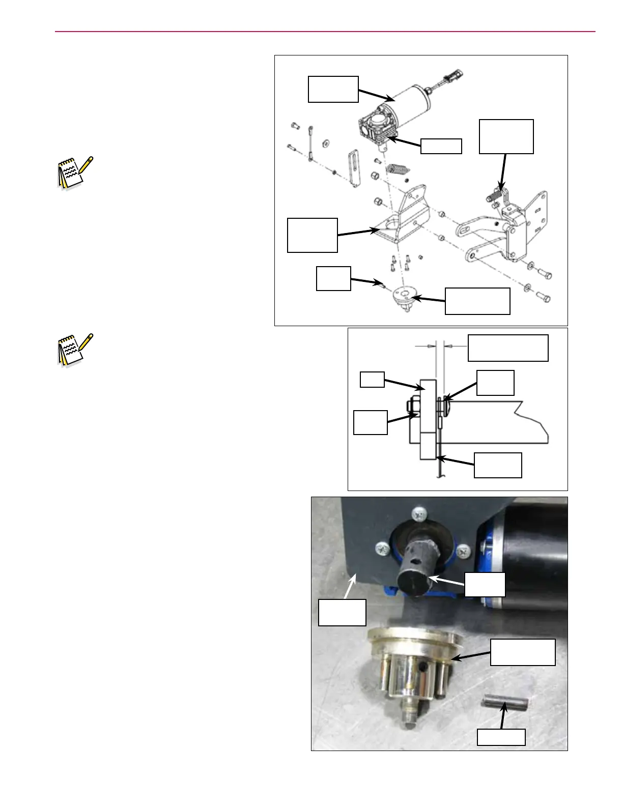
Note: When you reinstall the Cable Assembly to
the Arm on the side broom lift weldment,
leave a 0.19” ± 0.03” [4,8 mm ± 0,7 mm]
gap between the Phillips Screw and Arm to
allow the Cable Assembly to move freely on
the Phillips Screw.
Side Broom Hub
1. Remove the side broom motor assembly from the
machine.
2. Make sure the Motor Assembly and Side Broom
Hub Assembly are adequately supported, then
carefully drive out the Spring Pin.
3. Remove the Side Broom Hub Assembly from the
Gearbox Shaft.
4. Reinstall the Side Broom Hub Assembly by
following the above steps in reverse order.
5. Coat the Gearbox Shaft with Never-Seez® or
equivalent anti-seize compound before installing
the Side Broom Hub Assembly.
Motor
Bracket
Weldment
Motor
Assembly
Side
Broom Arm
Assembly
Side Broom Hub
Assembly
Spring
Pin
Gearbox
0.19” ± 0.03” [4,8
mm ± 0,7 mm]
Phillips
Screw
Cable
Assembly
Nyloc
®
Nut
Arm
Side Broom Hub
Assembly
Spring Pin
Gearbox
Shaft
Motor
Assembly