247Service Manual – CS7010™ 38 - Squeegee System
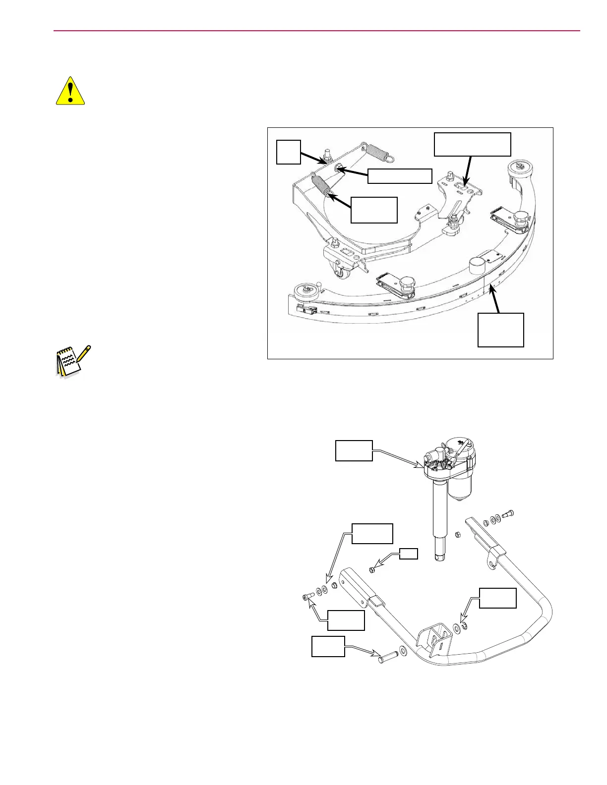
Squeegee Support Assembly
CAUTION: Disconnect the main battery connector before working near the drive wheel. If the
machine is unexpectedly powered on, the steering initialization routine can cause
serious injury.
1. Remove the Rear Squeegee Assembly.
2. Disconnect the Extension Springs from
the Squeegee Support Assembly using
a spring puller. (See the Special Tools
section.)
3. Remove the 3/4”-16 Screw holding the
Squeegee Support Assembly to the Rod
End.
4. Carefully remove the Squeegee Support
Assembly from the machine.
5. Reinstall the Squeegee Support
Assembly by following the above steps in
reverse order.
Note: Use removable thread sealer
when reinstalling the 3/4”-
16 Screw. Tighten the 3/4”-16 Screw to 270 ft/lbs.
Squeegee Lift Arm
1. Remove the rear squeegee assembly and
squeegee support assembly.
2. Disconnect the extension springs from the
squeegee lift arm.
3. Remove the pin, washers and E-clip connecting
the squeegee lift actuator to the squeegee lift
arm.
4. Remove the shoulder screws, at washers,
bushing and nyloc nuts connecting the front
brackets to the machine frame, then remove the
squeegee lift arm from the machine.
5. Reinstall the squeegee lift arm by following the
above steps in reverse order.
Rear
Squeegee
Assembly
3/4”-16 Screw
Extension
Spring (2)
Rod
End
Squeegee Support
Assembly
Lift
Actuator
Shoulder
Screw
Washers
& Bushing
Nut
Pin &
Washer
E-Clip &
Washer