69Service Manual – CS7010™ 04 - Control System
Power Modules
A2 Power Module 1
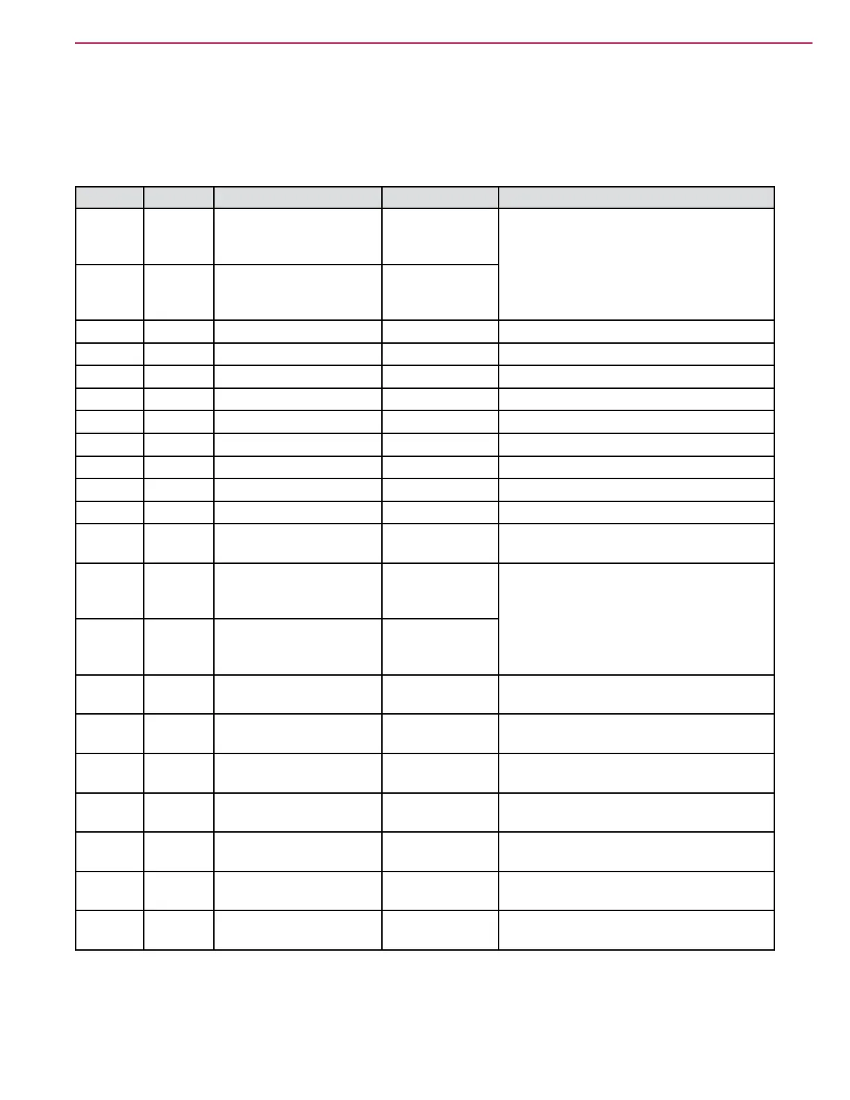
For clarity, some outputs listed in the table are out of sequence so that related functions can be grouped
together for those motors using 2-pin outputs.
Pin Wire Circuit Description Value/Condition Comments
J3- 1 ORN-BLK M7 Dump Door Actuator Close - 3.4 V
Rest - 1.1 V
Open-35.1
Motor function controlled by voltage
differencebetweenJ3-1andJ3-6.
Close:P1toP6=B+
Open:P1toP6=B-
Rest: P1 to P6 = same (0V)
J3- 6 ORN-GRY M7 Dump Door Actuator Close - 38 V
Rest - 1.1 V
Open-0.05V
J3- 2 BRN-BLU K2 Coil 0.84 V on
J3- 3 GRN-WHT
CAN0Low 2.3 V
J3- 4 YEL-WHT CAN 0 High 2.79 V
J3- 5 ORN-YEL Curtis Programmer 15.7 V
J3- 7 ORN-VIO Curtis Programmer 0.001 V
J3- 8 ORN-WHT Curtis Programmer 0.04 V
J3- 9 ORN KSI 38.14 V
(KeySwitchInput)
J3- 10 BLU-GRY M8ShakerMotor 35+volts Pulses positive voltage on and off
J3- 11 ORN-RED
M8ShakerMotor 0.01 Negative side is constant
J3- 12 BLK Battery Negative
(LowPower)
0.003 V Onevacuummotorrunning
J3- 13 TAN-VIO M6 Main Broom Actuator Up - 15.5 V
Rest - 1.1 V
Down-22.4V
Motor function controlled by voltage
differencebetweenJ3-13andJ3-14.
Up: P13 to P14 = B- (PWM)
Down:P13toP14=B+(PWM)
Rest: P13 to P14 = same (0V)
J3- 14 BLK-GRY M6 Main Broom Actuator Up - 0.01 V
Rest - 1.1 V
Down-38.1V
Lug- B- BLK Battery Negative (High
Power)
0.006 V Onevacuummotorrunning
Lug-B+ BLU-GRY Battery Positive
(HighPower)
38.26 V
Lug- M1 WHT-VIO M1 Main Broom Motor 38.2 V off
5.9 V on
PWM to Ground
Lug- M2 BRN-YEL M2 Dust Fan Motor 38.0 V off
0.03 V on
Lug- M3 WHT-BRN M3 L &R Side Broom
Motors control
38.1 V off
5.9 V on
PWM to Ground
Lug- M4 GRY-RED M4 Vacuum Motor 1
control
38.1 V off
5.9 V on
PWM to Ground
Lug- M5 ORN-BLU M5 Vacuum Motor 2
control
38.1 V off
5.9 V on
PWM to Ground