260Service Manual – CS7010™ 42 - Sweep System, Main
Circuit Description
Main Broom Actuator
The main broom actuator raises and lowers the main broom. Instead of the typical end limit switches, this
actuator provides analog position feedback to the Main Machine Controller. A potentiometer in the head
of the actuator returns a variable voltage between 0 and 3.3 volts back to the main controller. The main
controller interprets this voltage to determine the main broom position. The main controller commands
movement of the actuator via CAN Bus messages to Power Module #1 (A2).
Main Broom Motor
The main broom motor is driven by Power Module #1 by CAN Bus commands from the main controller. The
motor is active when the sweep system is active (broom lowered) and the drive pedal is out of the neutral
position.
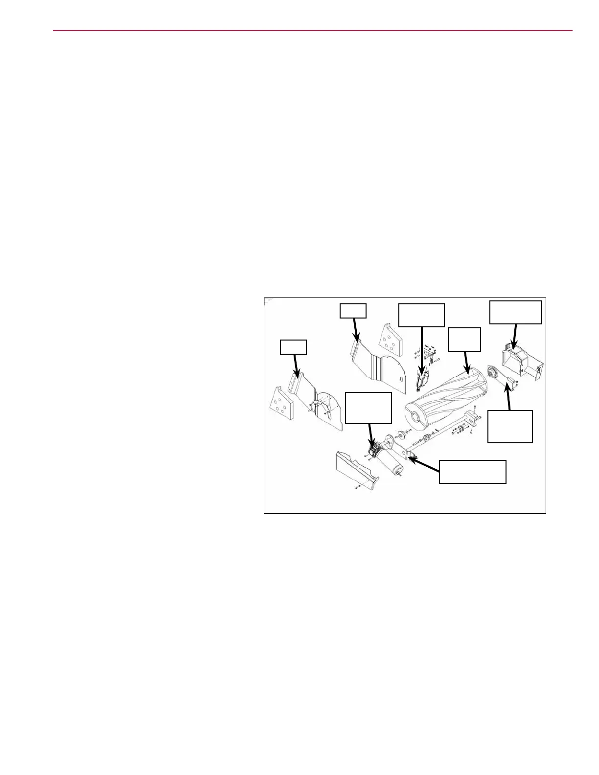
Component Locations
Main Broom and Drive Components
The main broom is supported by the broom
arm assembly and the broom support
weldment. The broom motor assembly drives
the main broom and is mounted to the broom
support weldment.
The broom lift actuator raises and lowers
the broom support weldment which pivots
on the machine frame to raise and lower the
attached main broom.
The broom door assembly swings out of
the way to allow access to the broom arm
assembly. The broom arm assembly is hinged
to allow the main broom to be removed from
the machine for maintenance or replacement.
The left and right skirts direct the debris
swept by the main broom into the hopper.
Main
Broom
Broom Door
Assembly
Broom Lift
Actuator
Broom Arm
Assembly
Broom Support
Weldment
Broom
Motor
Assembly
Skirt
Skirt