67Service Manual – CS7010™ 04 - Control System
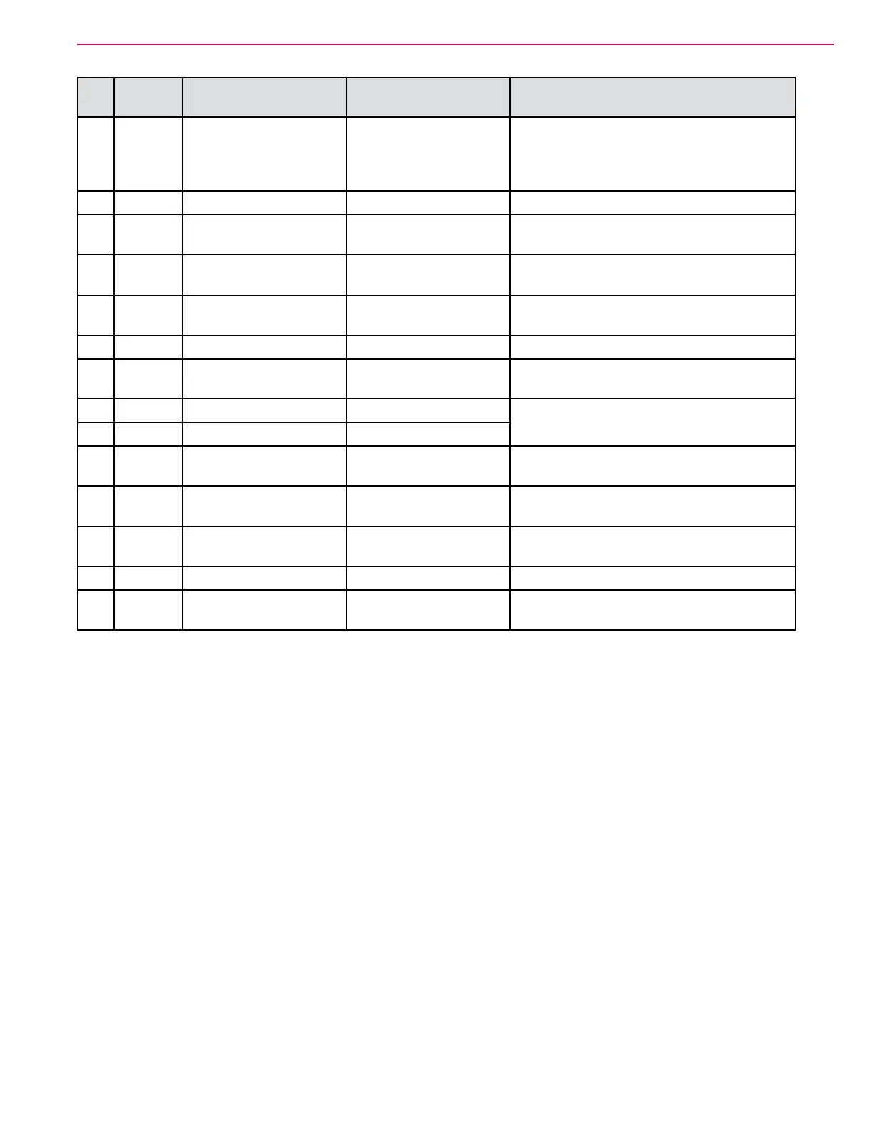
J1
Pin
Wire Circuit Description Value/Condition Comments
22 GRY Run Signal input 4.5 V Key on
0.018 Engine Running
Signal from engine controller. The run
signalisactivelowfortheLEVenginebut
all the other engines the run signal is high
(+12V).
23 ORN
KSI(KeySwitchInput) 37.9 V Key on
24 TAN-RED Tail lamp control Estimated 12V off
0V on
Not available on test machine
25 ORN-YEL LT5 Left Front Turn Estimated 12V off
0V on
Not available on test machine
26 BRN-RED M1 and L1 Dust Guard 37.8 V off
0.11 V on
27 BLK
BatteryNegativePower 0.001 V
28 RED-YEL M22 Solution Pump 37.8 V off
0.12 V on
29 VIO VACC2 37.9 V Key on
PositivebatterypowerthroughtheK1relay
30 GRY-ORN VACC2 37.9 V Key on
31 ORN-BLU LT9 Left Rear Turn/
Stop Lamp control
Estimated 12V off
0V on
Not available on test machine
32 YEL-GRN LT10 Right Rear Turn/
Stop Lamp control
Estimated 12V off
0V on
Not available on test machine
33 VIO-ORN M19 Extended Scrub
Pump
27.8 V off
0.06 V on
34 BLK
BatteryNegativePower 0.001 V
35 VIO-BRN H2 Horn 37.8 V off
0.12 V on