94Service Manual – CS7010™ 22 - Steering System
8. Disconnect the 2 wires from the E-stop switch.
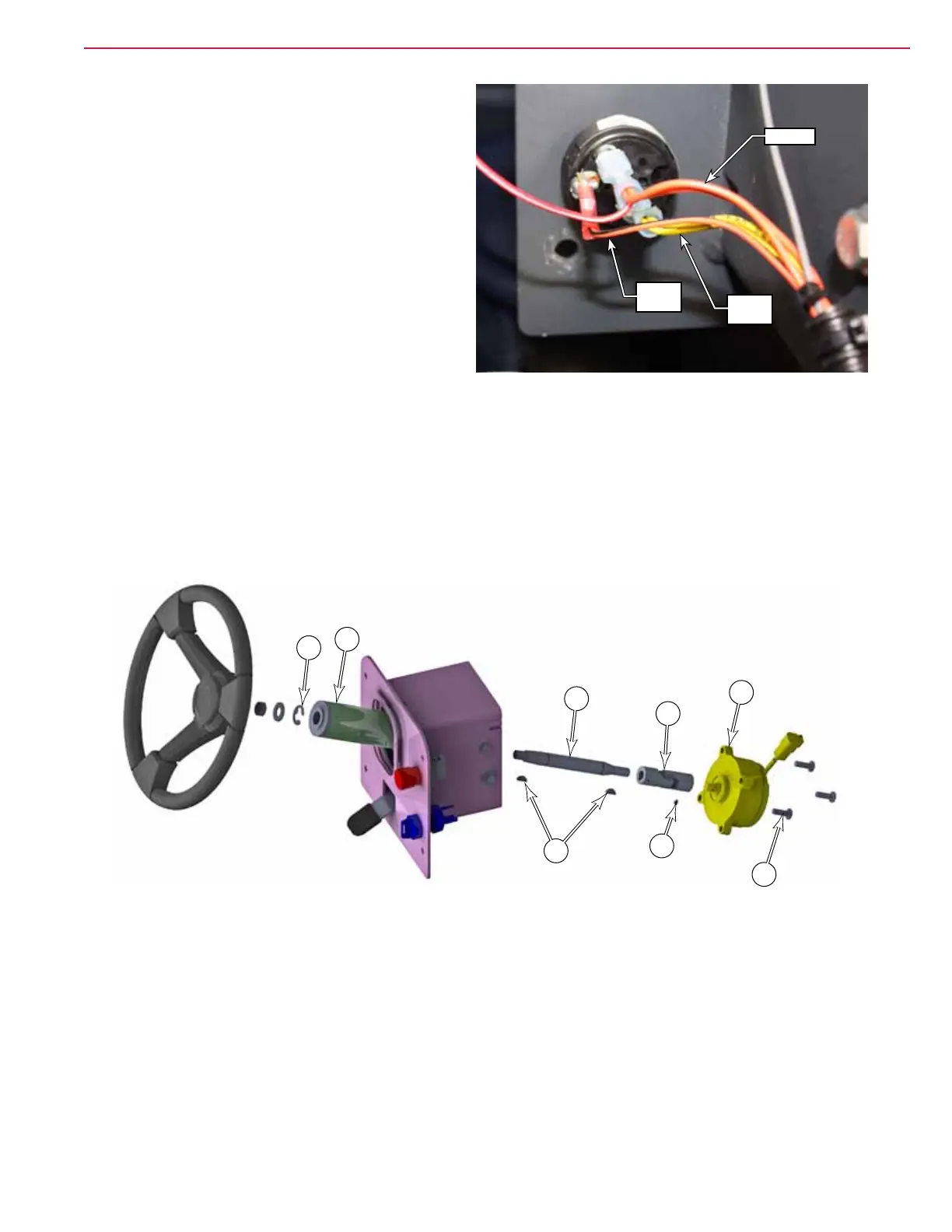
9. Disconnect the 3 wires from the ignition
switch. Make note of the wire positions for later
replacement.
10. Finish removing the steering assembly from the
machine.
11. Remove the E-clip (A) from the top of the steering shaft (C).
12. Remove the 3 screws (G) that secure the encoder (H) to the steering assembly.
13. Push the steering shaft (C) into the steering column (B), and remove the shaft, U-joint (F) and encoder
(H). Note that the connection between the U-joint and steering shaft is just a slip t. Pushing the shaft
out instead of pulling the encoder, makes it easier to keep the parts together and not lose the woodruff
key (D).
14. Loosen the setscrews (E) on the U-joint, and remove the encoder from the U-joint.
15. During reassembly, pre-assemble the steering shaft, woodruff key, U-joint, and encoder before inserting
the steering shaft into the steering column.
• Make sure to align the U-joint setscrews (E) with the hole in the encoder shaft. To ensure that the
setscrews are properly seated in the hole, they should protrude from the side of the U-joint body by
no more than 0.02”
• Make sure the woodruff key hasn’t fallen out during this step.
• Important: Do not add setscrews to the steering shaft side (C) of the U-joint. This side of the U-joint
must be a slip connection to prevent damage to the steering encoder.
Orange
Yellow
Brown
Violet
Green
A
C
F
E
H
G
D
B