and 52-30 Target Torque to 0, otherwise the change is
rejected for safety reasons.
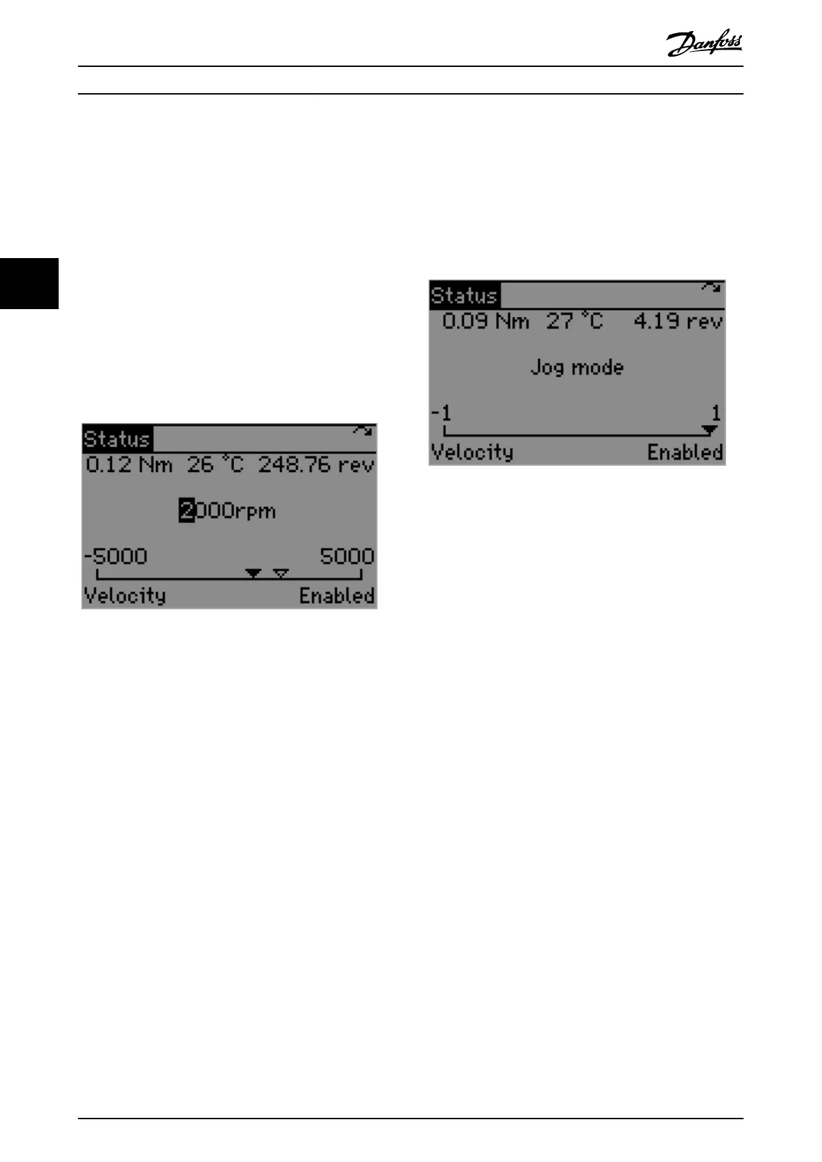
Velocity mode
The Hand On mode for velocity allows moving the shaft by
setting its target velocity. The functionality is provided by
the Status screen when the LCP is in Hand On mode and
the servo drive is in Velocity mode, as shown in
Illustration 4.15.
Like the general Status screen, this customized screen
contains readouts 1.1, 1.2, and 1.3, the mode of operation,
and the state of the servo drive. Furthermore, it contains a
numerical input eld and a gauge control for setting and
visualizing the target velocity. Edit the numerical value
above the gauge to set the target velocity. The unit for the
target velocity is specied by parameter 00-34 Unit for
velocity readout.
Illustration 4.15 Hand On Mode – Velocity
The minimum and maximum values of the gauge and
numerical input are dynamically updated from parameter
50-16 Max prole velocity. Set the target velocity value and
press the [OK] key to apply the velocity according to the
velocity conguration. Switch to the device to state
Operation enabled before performing velocity movement.
The velocity behavior depends on the values of the
following parameters. Set them accordingly before using
the Velocity functionality.
•
Parameter 50-16 Max prole velocity
•
Ramp conguration
- Parameter 52-21 Prole acceleration
(default: 1000 RPM/s)
- Parameter 52-22 Prole deceleration
(default: 1000 RPM/s)
•
Parameter 52-23 Application torque limit
Jog mode
The Jog mode turns the motor at a pre-dened velocity by
using the [
◀
] and [
▶
] keys on the LCP. The functionality is
based on the Prole velocity mode of operation.
Illustration 4.16 depicts the LCP Status screen in Hand On
mode shown when Jog mode is active. The text “Jog
mode” is shown in the center of the screen to indicate that
the Jog functionality is active. Below this text, a control
gauge with limits of –1 and 1 is shown:
•
–1 indicates jog in negative direction.
•
0 indicates standstill.
•
1 indicates jog in positive direction.
For more information on the servo drive directions, refer to
parameter 52-04 Drive Mirror Mode.
Illustration 4.16 Jog Mode
The Jog behavior depends on the values of the following
parameters. Set them accordingly before using the Jog
functionality.
•
Parameter 52-71 Jog speed
(default: 100 RPM)
•
Parameter 50-16 Max prole velocity
•
Ramp conguration
- Parameter 52-21 Prole acceleration
(default: 1000 RPM/s)
- Parameter 52-22 Prole deceleration
(default: 1000 RPM/s)
•
Parameter 52-23 Application torque limit
Jog in positive direction is performed when the [
▶
] key is
pressed – and stopped when it is released.
Jog in negative direction is performed when the [
◀
] key is
pressed – and stopped when it is released.
Position mode
The Hand On mode functionality for positioning moves the
shaft to an absolute or relative position, depending on the
value of LCP parameter 52-11 Positioning type (default
value: relative). The functionality is provided by the Status
screen when the LCP is in Hand On mode and the servo
drive is in Position mode, as shown in Illustration 4.17.
In addition to the information of the general Status screen,
this customized screen contains a numerical input eld and
a gauge control for setting and visualizing the target
position. The target position is set by editing the numerical
value above the gauge. The unit for the target position is
specied by parameter 00-33 Unit for position readout.
Local Control Panel (LCP) O...
VLT
®
Integrated Servo Drive ISD
®
510 System
102 Danfoss A/S © 01/2017 All rights reserved. MG36D102
44

 Loading...


