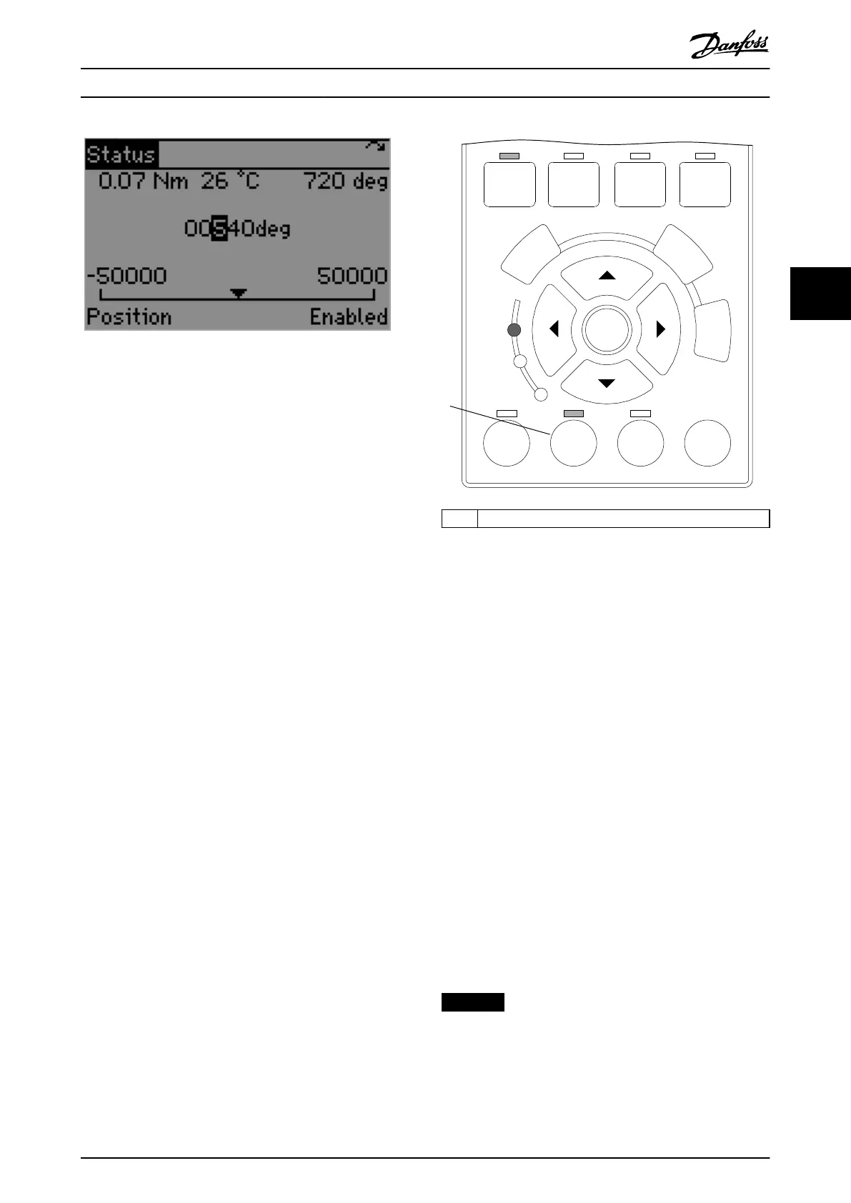
Illustration 4.17 Hand On Mode – Positioning
Set the target position and press the [OK] key. Now the
shaft moves according to the positioning conguration.
Before performing positioning, switch the device to state
Operation enabled. The positioning takes place
immediately. The positioning behavior depends on the
values of the following parameters. Set them accordingly
before using the Positioning functionality.
•
Parameter 52-12 Prole velocity
(default: 100 RPM)
•
Ramp conguration
- Parameter 52-13 Prole acceleration
(default: 1000 RPM/s)
- Parameter 52-14 Prole deceleration
(default: 1000 RPM/s)
•
Parameter 52-11 Positioning type
(default: relative)
•
Parameter 52-15 Application torque limit
•
Limits
- Parameter 50-30 Min position range limit
(default: 0 deg)
- Parameter 50-31 Max position range limit
(default: 0 deg)
O mode
Press the [O] key when the servo drive is in Hand On
mode to change the servo drive state to Switch on
Disabled. If the motor is not in standstill, it stops according
to the selected behavior set in parameter 50-48 Shutdown
option code.
When entering O mode from Hand On mode, the selected
Hand On functionality (position, velocity, jog, or intertia) is
retained. Therefore, the same status screen as in Hand On
mode is shown after switching to O mode.
Illustration 4.18 depicts the LCP after switching from Hand
On mode with velocity to O mode. The LED above the
[O] key indicates that O mode is active – there is no
other indication on the LCP display.
130BE919.10
On
Alarm
Warn.
Back
Cancel
Info
OK
Quick
Menu
Main
Menu
Alarm
Log
Auto
On
Reset
Hand
On
O
Status
1
1 Hand On mode o
Illustration 4.18 Hand On Mode - O
Inertia measurement
When Hand On mode is active, the LCP can be used to
perform inertia measurement. The functionality is
contained in parameter group 52-6* Inertia Measurement.
The group contains the following parameters:
•
Parameter 52-60 Measured inertia to read the
measurement result. Positive values indicate that
the measurement was carried out successfully
and the inertia is shown in kg x m
2
. Negative
values indicate a measurement error.
•
Parameter 52-61 Inertia measurement velocity and
parameter 52-62 Inertia measurement torque for
conguration of the inertia measurement
procedure.
•
Parameter 52-63 Start inertia measurement to
perform the measurement operation. Set this
parameter to 1 to trigger the operation.
•
Parameter 52-64 Inertia measurement result to
show the measurement result code and
description if an error occurs during the inertia
measurement.
NOTICE
The measured inertia is not automatically transferred to
the control loop parameter set.
Local Control Panel (LCP) O... Programming Guide
MG36D102 Danfoss A/S © 01/2017 All rights reserved. 103
4 4

 Loading...


