Illustration 5.22 Oine Device Window
All devices that are added to the project are shown inside
the Device Environment window as root nodes of the tree
shown (see Illustration 5.8). Each device is denoted by
using its device type and node ID in brackets. The sub-tool
categories and the sub-tools themselves are shown as
child nodes of the respective device.
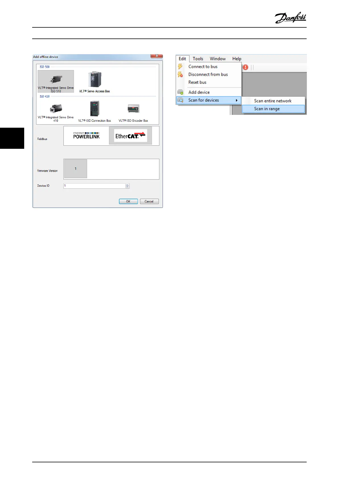
5.6.5 Scan for Devices
When connected to a network, the ISD Toolbox can scan
for available devices on the network and add them to the
Device Environment. The scanning procedure is triggered by
using the menu [Edit → Scan for devices] or via the Scan
for Devices icon in the toolbar.
Depending on the eldbus, the scan procedure for the
whole ID range can take some time. To limit the maximum
time for the procedure, it is possible to scan only within a
certain ID range (cyclic Ethernet POWERLINK
®
). This can be
done via menu [Edit → Scan for devices → Scan in range].
This shows a window where the minimum and maximum
IDs to search for can be specied. Use the menu [Edit →
Scan for devices → Scan entire network] to search the
entire network (CAN, EtherCAT
®
, acyclic Ethernet
POWERLINK
®
, and Ethernet via PLC).
Illustration 5.23 Scan in Range Menu Item
When the scan procedure is triggered, a window indicating
the scan progress and the IDs found on the eldbus are
shown. When the scan is completed, the Select Devices
window shows all found devices and the desired devices
can be added to the Device Environment. The scan
procedure can be stopped at any time and the devices
already found can be added to the Device Environment.
5.7 Sub-Tools
5.7.1 Parameter List (Servo Drive and SAB)
The Parameter List sub-tool shows all available parameters
of a device. It is the main tool designed for browsing
parameters and reading and writing parameter values on
an online device. The Parameter List shows all parameters
in table format containing both parameter information and
parameter values.
There are 2 parameter views available in the Parameter List:
•
Object dictionary view
•
Parameter view
When the Object dictionary view is selected, the Parameter
List shows the parameters with their unique index-sub-
index identier (see Illustration 5.24). When the Parameter
view is selected, the Parameter List shows the parameters
with their unique parameter number. The parameter
groups tree at the left of the sub-tool window is used to
lter the shown parameters according to their respective
categories. Selecting the root node of the tree disables any
lters and shows all parameters.
Operation with ISD Toolbox
VLT
®
Integrated Servo Drive ISD
®
510 System
122 Danfoss A/S © 01/2017 All rights reserved. MG36D102
55

 Loading...


