In the example depicted in Illustration 5.29, the real-time
task sampling is 8 kHz (125 µs between 2 samples), the
fast task sampling is 4 kHz (250 µs between 2 samples),
and the slow task sampling is 2 kHz (500 µs between 2
samples). These sampling rates are also shown for oine
devices.
The Subsampling eld controls the subsampling level of
the trace, which is a factor applied to the sampling rate:
for example, using a fast task sampling with 250 µs
between 2 samples and subsampling 3, the resulting trace
has 750 µs between 2 samples.
The
eld Samples controls the length of the trace in terms
of the number of sample counts per channel. The
maximum number allowed depends on the trace buer of
the device and the number of channels to trace. For
example, if a device can trace a total maximum of 32000
samples and 4 channels are congured to be traced, then
the maximum number of samples per channel is 8000.
5.7.3.2 Triggering
The triggering functionality of the devices is visualized by
the Triggering control on the left side of the Scope. Specify
here whether the trace should be triggered by a certain
event, or if the trace should be started instantly.
Due to its real-time nature, the triggering functionality is
entirely implemented on the devices – the Scope only
controls and visualizes the triggering conguration on the
devices and does not implement any triggering logic.
A trigger event is dened by a trace signal, whose value is
exceeded in a positive or negative direction.
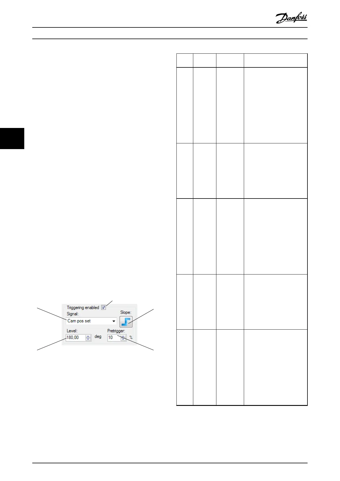
Illustration 5.30 shows an example of a trigger event that is
dened by the trace signal Cam pos set exceeding the
value of 180 degrees in a positive direction (rising slope).
Illustration 5.30 Triggering Control
Callout Field
name
Description Function
1 Signal Drop-down
list of
trigger
signals
Contains all available signals
on the device and selects the
signal to be used for
triggering. The behavior of the
Signal drop-down list is
exactly the same as the
behavior of the Signal name
drop-down list in the Signal
chooser control. It is not
necessary to also trace the
trigger signal.
2 Triggering
enabled
Checkbox to
enable/
disable
triggering
Controls whether triggering
should be used on the device.
If triggering is disabled, then
the trace is started instantly
after activation (pressing the
Run button). Also, all other
elds of the Triggering control
are disabled.
3 Slope Trigger
slope
Controls the direction from
which the Level value should
be reached in order for the
trace to be triggered: a rising
slope means that the value
should be reached in a
positive direction, and a falling
slope means that the value
should be reached in a
negative direction. The default
value of the button is rising.
4 Pretrigger Pretrigger Sets the number of samples to
be traced before the trigger
event occurs. The value is
given as a percentage of the
number of samples per
channel (eld Samples). The
default value of the eld is
10%.
5 Level Trigger level Shows the value at which the
trace should be triggered
(depending on the trigger
slope conguration). If
dened, the unit of the
selected trace signal is shown
on the right of the Level eld.
The trigger level eld is a
decimal value with 2 decimal
places. The default value of
the eld is 0.
Table 5.8 Legend to Illustration 5.30
Operation with ISD Toolbox
VLT
®
Integrated Servo Drive ISD
®
510 System
126 Danfoss A/S © 01/2017 All rights reserved. MG36D102
55

 Loading...


