5.7.7.5 CAM Prole Window Overview
The CAM Prole window is the graphical visualization and
editing user interface for both basic and advanced CAM
proles. For every CAM prole, there is 1 CAM Prole
window that visualizes all CAM elements in the prole.
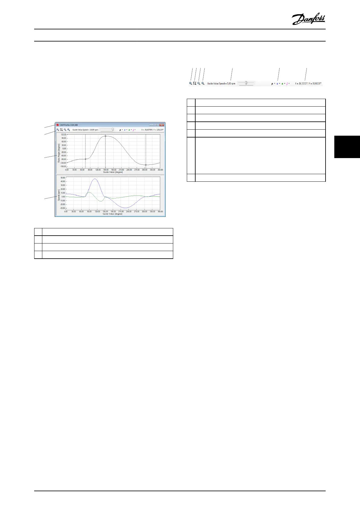
Illustration 5.61 shows the CAM Prole window and its 4
basic elements.
1 Window title
2 Toolbar
3 Rotor angle plot area
4 Velocity, acceleration, and jerk plot area
Illustration 5.61 CAM Prole Window
The horizontal scale and horizontal view oset of both
graphs are always synchronized. This allows easy visual
comparison between the rotor position and its derivatives
(velocity/acceleration/jerk).
The vertical scales of the graphs are independent from
each other and can be varied according to the visualization
scenario.
The following sections describe the CAM Prole window
elements.
Toolbar
The CAM Prole window toolbar contains visualization
functionalities that do not aect the shown CAM prole
itself. Illustration 5.62 shows the CAM Prole window
toolbar and its components.
1 Zoom to show the entire prole
2 Marquee zoom
3 Zoom in
4 Zoom out
5 Guide value speed simulation control
6 Unit selection:
p = position
v = velocity
a = acceleration
j = jerk
7 Mouse cursor position
Illustration 5.62 CAM Prole Window Toolbar
The button Zoom to show the entire prole calculates the
best zoom to show the entire CAM prole and ll both
graphs. The vertical zooms of the 2 graphs are calculated
independently.
The button Marquee zoom enables a region of the rotor
angle graph to be selected to zoom to. The marquee
implementation follows the standard marquee functionality
known in most existing editing programs.
The Zoom in and Zoom out buttons respectively perform
zoom in and zoom out on both graphs.
The Guide value velocity track bar changes the guide value
speed used to visualize the event segments with. The track
bar can have values between 0 and the Maximum guide
value velocity parameter of the CAM prole.
The Unit selection drop-down items allow changing the
position, velocity, acceleration, and jerk units that are used
for visualization. The p, v, a, and j symbols are shown with
the color used for drawing the respective graph.
The Mouse cursor position area shows the value at which
the mouse cursor is pointing (position/velocity/
acceleration/jerk).
Rotor angle plot area
The rotor angle plot area is a 2-dimensional plot of real
numbers to show the rotor angle (vertical axis) in relation
to the guide value (horizontal axis). The guide value axis is
given in degrees, and the rotor angle axis is given in the
unit specied on the CAM Editor window toolbar. The
horizontal axis is labeled as Guide Value [degrees] and the
vertical axis is labelled as Rotor Angle [unit], where [unit]
denotes the user-dened position unit.
The rotor angle graph is rendered in the rotor angle color
specied in the Options window. The default color is black.
The rotor angle graph shows all CAM elements of the
Operation with ISD Toolbox Programming Guide
MG36D102 Danfoss A/S © 01/2017 All rights reserved. 143
5 5

 Loading...


