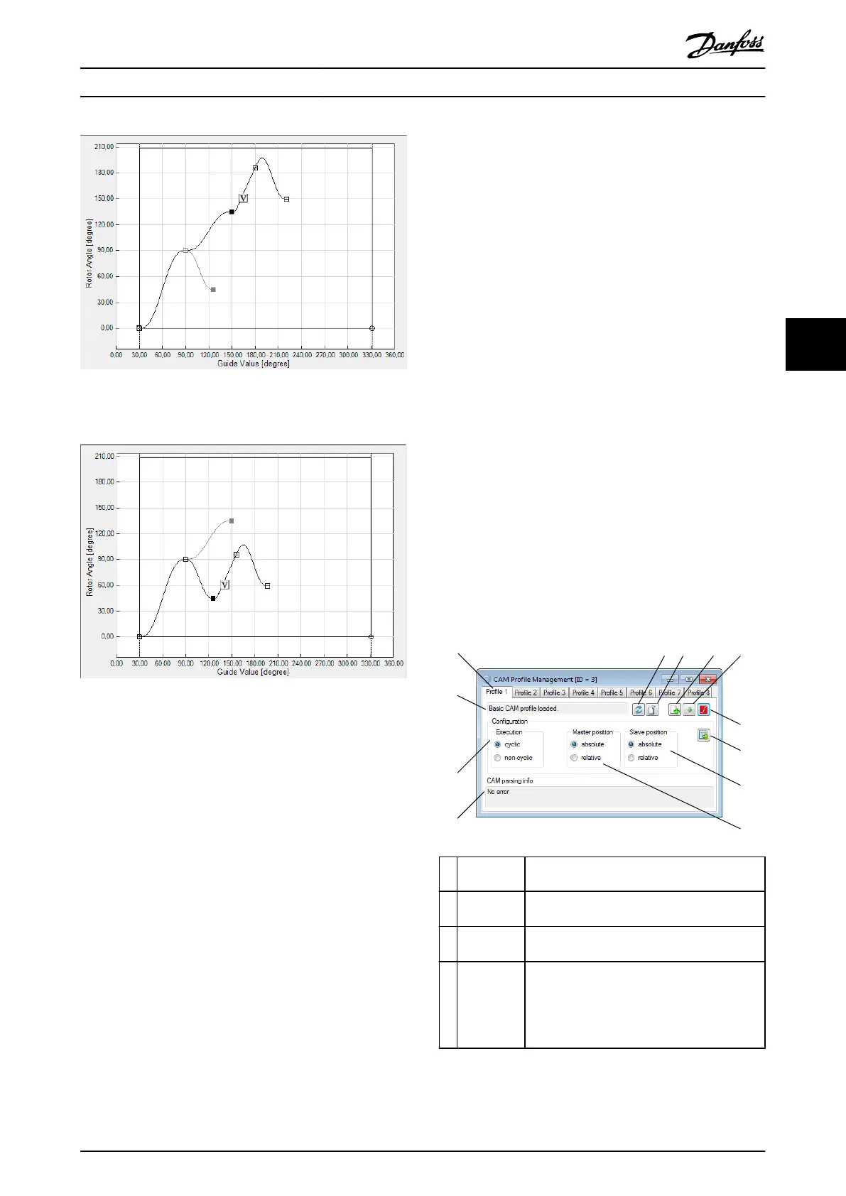
Illustration 5.82 Following Event Segments Depending on the
Selected Path 1
Illustration 5.83 Following Event Segments Depending on the
Selected Path 2
Sanity check
The Sanity check for advanced CAM proles helps to
identify potential problems and risks in a prole. The sanity
check identies and shows problems in 2 categories:
•
Warning: Shown to create awareness of certain
behavior.
•
Error: Prevent the export of the CAM prole.
The following situations result in a warning:
•
Jump in position: Shown whenever 2 succeeding
segments, connected by a node, dene dierent
End position and Start position.
•
Jump in velocity: Shown whenever 2 succeeding
segments, connected by a node, dene dierent
End velocity and Start velocity.
•
Jump in acceleration: Shown whenever 2
succeeding segments, connected by a node,
dene dierent End acceleration and Start
acceleration.
The following situations result in an error:
•
No data or incomplete data: <2 nodes or <1
segment have been specied in the CAM prole.
•
No starting node: No guide node with ID 0 is
specied in the CAM prole.
5.7.7.8 Standalone Emulation of the CAM
Editor
The ISD Toolbox is loaded and the CAM Editor is automat-
ically shown and maximized when a .cam or a .camproj is
double-clicked in Microsoft
®
Windows.
An
oine drive device is automatically added to the device
environment of the ISD Toolbox, rather than attempting to
connect to an existing physical device. Therefore, it cannot
be used to transfer CAM proles to a servo drive.
5.7.8 CAM Prole Management
There are multiple tasks for managing CAM proles on the
servo drive: sending CAM
prole les to the servo drive,
triggering the parsing procedure in the servo drive, and
conguring the proles. These tasks are done by using the
sub-tool CAM Prole Management. The CAM Prole
Management sub-tool contains a tab control with a
separate tab for every CAM prole slot on the servo drive
(1–8), see Illustration 5.84.
2
3 4
5
6
7
8
9
1
12
11
10
130BE821.10
1 Prole tabs
(1–8)
Provides information on the proles.
2 Refresh
button
Reads the state for the selected prole from
the servo drive and updates the user interface.
3 Parse
button
Triggers the parsing of the selected prole on
the servo drive.
4 Send File
button
Shows an Open File window for selecting
a .cam le and transmits it to the servo drive.
The parsing of the prole is not started
automatically and must be triggered by using
the Parse button.
Operation with ISD Toolbox Programming Guide
MG36D102 Danfoss A/S © 01/2017 All rights reserved. 157
5 5

 Loading...


